
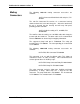
Technical data

1260-118/-118A User Manual Publication No. 980824-118 Rev. A
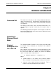
Module Operation 3-4 Astronics Test Systems
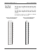
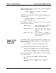
So, for our example, the first control register is located at:
205C01 Control Register 0, controls channels 0
through 7
The second control register is located at:
205C03 Control Register 1, controls channels 8
through 15
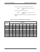
Tables 3-1 and 3-2 show the channel assignments for each control
register.
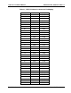
Table 3-1, 1260-118 Control Register Channel Assignments
Control
Register
Channels
Bit 7
(MSB)
Bit 6 Bit 5 Bit 4 Bit 3 Bit 2 Bit 1
Bit 0
(LSB)
0 7 6 5 4 3 2 1 0
1 15 14 13 12 11 10 9 8
2 23 22 21 20 19 18 17 16
3 31 30 29 28 27 26 25 24
4 39 38 37 36 35 34 33 32
5 47 46 45 44 43 42 41 40
6 55 54 53 52 51 50 49 48
7
63
62
61
60
59
58
57
56
8 71 70 69 68 67 66 65 64
9 79 78 77 76 75 74 73 72