
Technical data

Publication No. 980824-118 Rev. A 1260-118/-118A User Manual
Astronics Test Systems Installation Instructions 2-3
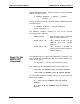
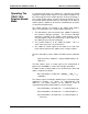
Front Panel
Connectors
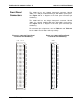
The 1260-118 has one 160-pin front-
panel connector, labeled
J200. It is a 160-pin, modified DIN style, with 0.025” square posts.
See Figure 2-2
for a diagram of the front panel connector pin
numbering.
The 1260-118A has one 64-pin front-
panel connector, labeled
J200. It is a 64-
pin, modified DIN style, with 0.025” square posts.
See Figure 2-3 for a diagram of the front panel
connector pin
numbering.
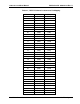
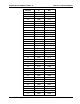
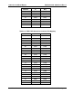
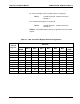
For connector pin assignments, refer to Table 2-1 and Table 2-2
for the 1260-118 and 1260-118A respectively.
Figure 2-2, 1260-118 Front-Panel
Connector Pin Numbering
Figure 2-3, 1260-118A Front-Panel
Connector Pin Numbering
a b c d e
31
30
29
28
27
26
25
24
23
22
21
19
18
17
16
15
14
13
12
11
10
9
8
7
6
5
4
3
2
1
20
32
a b
31
30
29
28
27
26
25
24
23
22
21
19
18
17
16
15
14
13
12
11
10
9
8
7
6
5
4
3
2
1
20
32