
Technical data

Publication No. 980824-118 Rev. A 1260-118/-118A User Manual
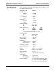
Astronics Test Systems Specifications 1-5
This is acceptable power dissipation for an individual plug-in
module. If five additional modules are likewise loaded, then the
overall carrier dissipation is approximately 36
W, which is well
within the cooling available in any commercial VXIbus chassis. In
practice, rarely are more than 25%
of the module’s relays
energized simultaneously, and rarely is full rated current run
through every path. In addition, the actual contact resistance is
typically one-half to one-
fourth the specified maximum, and
temperatures are normally not at the rated maximum. The power
dissipated by each plug-in should be no more than 15 W if all six
slots are used simultaneously. This yields the following guideline:
0.5 A Max. 80 relays closed
1.0 A Max. 14 relays closed
2.0 A Max. 4 relays closed
Most users of a signal-type switch, such as the 1260-118, switch
no more than a few hundred milliamperes and are able to energize
all relays simultaneously, should they so desire. The numbers in
the above table represent worst-case, elevated-temperature, end-
of-life conditions.
Additionally, if fewer plug-in modules are used, more power may
be dissipated by the remaining cards. By using a chassis with high
cooling capacity, such as the 1261B, almost any configuration may
be realized.
About MTBF
The 1260-118 MTBF is
783,668 hours, calculated in accordance
with MIL-HDBK-217E, with the exception of the electromechanical
relays. The MTBF for the 1260-
118A will be the same or better
depending on the number of relays engaged. Relays are excluded
from this calculation because relay life is strongly dependent upon
operating conditions. Factors affecting relay life expectancy are:
1. Switched voltage
2. Switched current
3. Switched power
4. Maximum switching capacity
5. Maximum rated carrying current
6. Load type (resistive, inductive, capacitive)
7. Switching repetition rate
8. Ambient temperature