
User`s manual


User’s Manual 51
A.6 Jumper Configurations
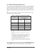
Figure A-6 shows the header locations used to configure the various RCM2000 options
via jumpers.
Figure A-6. Location of RCM2000 Configurable Positions
Table A-6 lists the configuration options.
NOTE: The jumper connections are made using 0 Ω surface-mounted resistors.
Table A-6. RCM2000 Jumper Configurations
Header Description Pins Connected
Factory
Default
JP1 SRAM Size
1–2 128K/256K
RCM2010
RCM2020
2–3 512K RCM2000
JP2 Flash Memory Size
1–2 128K/256K
×
2–3 512K
JP3 Flash Memory Bank Select
1–2 Normal Mode
×
2–3 Bank Mode
Top Side
175-0201
JP2
JP3
JP1
Bottom Side