— R9 Technology G200 Gateway Overview This manual provides an overview of R9 Technology’s G200 Gateway.
Document Revision Date 4/20/2019 Version Number V0.
Table of Contents 1 R9 Technology Device Description................................................................................................................... 4 1.1 2 G200 Cellular Gateway Information ......................................................................................................... 4 1.1.1 Powering the G200 Gateway ............................................................................................................... 5 1.1.2 Gateway Interfaces ................
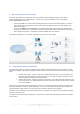
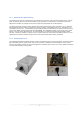
1 R9 Technology Device Description This section describes R9 Technology’s IOT devices, specifically the G200 Gateway (Picogate), and the SN400 (FCC ID:2AQM2SN400) sensor node (Piconode). Various sensor types are available to connect to the SN400 (FCC ID:2AQM2SN400) sensor node. The Picogate, G200, is a compact cellular gateway targeted at low cost data collection applications.
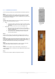
1.1.1 Powering the G200 Gateway The gateway device requires a standard 120V AC outlet for power. Therefore, it will need to be installed near an open AC outlet. The gateway device should also be installed as high as possible on a wall or beam, and away from large metal objects when possible. The gateway has four holes on upper and lower flanges for use with fasteners. The G200 gateway also provides a Lithium Polymer battery-based power backup system. The battery is 3.
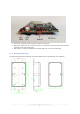
1. 2. 3. 4. 1.1.3 Reset Button – Resets the G200 to power on settings. Power Port – 5V-12V DC power can be input using a DC Jack input. Micro-USB – USB port to use as a generic interface. 5V USB power can also be used to power the G200 (alternative to DC power supply input). SIM Card Slot – Location to install the carrier specific SIM card. This is done at the factory. Gateway Dimensions The diagram below shows the dimensions of the G200 gateway product. All dimensions are in millimeters.
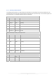
1.1.4 Gateway LED Definition The gateway product provides one external red/green LED indicator to communicate the status of the gateway to a user. The LED sequences through three modes below with a slight delay (LED out) between stages. After a final long pause, the three modes repeat. The gateway LED status loop runs continuously.
2 Picogate Installation 2.1 Required Items Items included with the G200: • Qty 01, G200 Gateway • Qty 01, 6’ Power supply (corded) • Note: The data service SIM card is pre-installed at the factory. Additional items required depending on the mounting option selected for each node. • Qty 02, Phillips head sheet rock screws, #10x1” • Option – Velcro tape kit (replacement for sheet rock screw gateway attachment) • Small Phillips head screw driver • Velcro Tape/Tie wraps (optional for cable routing) 2.
2.3 Installation Instructions Once the mounting location has been identified follow the installation steps below: Step 1 Before physically installing the node, gateway and sensors ensure the units have good reception in the general area of install (using actual gateway to node data transfers, see User Guide). If reception is poor an additional site survey will need to be completed prior to installation. Step 2 Determine which mounting method to use.
3 FCC Statement Compliance Statement (Part 15.19) This device complies with Part 15 of the FCC Rules. Operation is subject to the following two conditions: 1. This device may not cause harmful interference, and 2. This device must accept any interference received, including interference that may cause undesired operation. Warning (Part 15.21) Changes or modifications not expressly approved by the party responsible for compliance could void the user’s authority to operate the equipment.