
User's Manual

Mini 30mW
User’s Manual
R-Tron., Inc. 14/15 page
4. Block Diagram
Duplexer
PLL:Variable
RF Input
RF Output
15dBm/Total
Duplexer
PLL:Variable
-55dBm/Total
SAW
Attenuator
SAW
SAW
PLL:VariablePLL:Variable
SAW
Attenuator
SAW
SAW
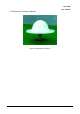
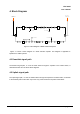
Figure 4.1 Block Diagram of Band Selective Repeater
Figure 4.1 shows a block diagram of a band selective repeater. This diagram is applicable to
repeaters for CDMA systems.
4.1 Downlink signal path
The downlink signal path, i.e. from the base station through the repeater to the mobile station, is
described for Mini 30 in the above block diagrams.
4.2 Uplink signal path
The uplink signal path, i.e. from the mobile station through the repeater to the base station, is identical
to the downlink path but the other way round. Only some levels and component values differ.