Mini 30mW User’s Manual
Mini 30mW User’s Manual Copyright Copyright of this manual belongs to R-TRON, Inc. Reproduction, distribution or revision of part or all of contents in this manual in any form without written permission of R-TRON, Inc. is prohibited. Registered Trademark R-TRON are registered trademarks of R-TRON, Inc. Other products and company names mentioned herein this manual might be trade marks or trade names of their respective owners.
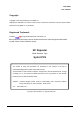
Mini 30mW User’s Manual Revision History Version Date of revision V0.1 Agust.11, 2005 Reason for revision Revision Description RF EXPOSURE INFORMATION The antenna used for this transmitter must not exceed 12dBi and must be installed to provide a minimum separation distance of 20cm from all persons. R-Tron., Inc.
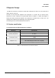
Mini 30mW User’s Manual Contents 1. Overview -----------------------------------------------------------------------6 2. Repeater Design ----------------------------------------------------------7 2.1 System specifications --------------------------------------------------7 1. Mechanical and Environmental conditions --------------------------7 2. System Electrical Specifications ---------------------------------------7 A. Mini 30 (30mW) Repeater ------------------------------------------------7 B.
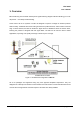
Mini 30mW User’s Manual 1. Overview Mini 30 will bring in those weak cellular phone signals reducing dropped calls and allowing you to use cell phones ...even deep inside a building. At the heart of all of our systems is a Mini 30 designed to improve coverage for wireless products within a facility.
Mini 30mW User’s Manual 2 Repeater Design The Mini 30 is housed in an aluminum chassis that is waterproof for indoor use. The chassis has a design suited for indoor use. The Mini 30 has several RF amplifiers and components on a board with an aluminum body. Furthermore, the RF components are implemented within RF CMOS IC or MMIC technologies. A board that contains several RF amplifiers and components is shielded under a metal cover. This amplifier board is different types depending on the supported system.
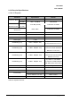
Mini 30mW User’s Manual 2.1.2 Electrical Specifications A. Mini 30 Repeater Parameter Frequency Band Specification Remark Down Link 1930 – 1990 MHz Total 60 MHz Up Link 1850 – 1910 MHz Total 60 MHz +14.8 dBm (30mW) Total Power on CDMA MAX. 5 dBm Total Power on CDMA Transmit Down Link Maximum Power Up Link Output Power on Coupled Service Port Gain 70dB ± 1 dB Gain Range 60 ~ 70dB Gain Step 10 dB (1 dB Step) Noise Figure < 5 dB Bandwidth(Type 1) 5 MHz BW(Max.
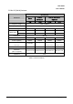
Mini 30mW User’s Manual B. Mini 30 (30mW) Antenna Specification Parameter Donor Yagi Internal External Distribution Distribution (Optional) Patch Patch Frequency range 1850 - 1990MHz Frequency bandwidth 140MHz Antenna gain Beam width Omni Min. 12dBi 2dBi 8dBi 2dBi Horizontal Min. 28° 70° 70° 360° Vertical Min. 28° 70° 70° 70° Polarization Vertical VSWR Max. 1: 1.5 Max. 1 : 1.3 Max. 1 : 1.3 Max. 1 : 1.
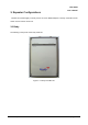
Mini 30mW User’s Manual 3. Repeater Configurations The Mini 30 consists largely of a body and an AC to DC SMPS Adapter. The body of the Mini 30 has an RF unit, and a main control unit. 3.1 Body The following is the picture of the body of Mini 30. Figure 3.1 A body of the Mini 30 R-Tron., Inc.
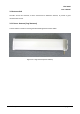
Mini 30mW User’s Manual 3.2 Antenna Unit The Mini 30 has two antennas, a donor antenna and a distribution antenna, to provide a good communication service. 3.2.1 Donor Antenna (Yagi Antenna) A donor antenna is used for receiving the transmitted signal from a base station. Figure 3.2 A Yagi antenna (Donor antenna) R-Tron., Inc.
Mini 30mW User’s Manual 3.2.2 Distribution Antenna A distribution antenna serves to transmit the amplified signal to individual mobile station in the shaded area. A. Internal Patch Antenna a. Rear view b. Front view Figure 3.3 Internal Patch Antenna B. External Patch Antenna (Optional) Figure 3.4 External Patch Antenna R-Tron., Inc.
Mini 30mW User’s Manual C. External Omni Antenna (Optional) Figure 3.5 External Omni Antenna R-Tron., Inc.
Mini 30mW User’s Manual 3.3 AC to DC SMPS Adapter A SMPS Adapter supply DC power to an Mini 30. Figure 3.6 AC to DC SMPS Adapter A. Specification overview Item Input Voltage AC to DC Output AC 90 to 264V 50/60Hz ±5% DC 12V Output Voltage Variation Ratio: less than ±5% Current 3.0A Efficiency 75% Min. at full load Power 36Watts Table 3.1 The specification of AC to DC SMPS Adapter R-Tron., Inc.
Mini 30mW User’s Manual 4. Block Diagram RF Output 15dBm/Total RF Input -55dBm/Total SAW SAW SAW Attenuator PLL:Variable PLL:Variable Duplexer Duplexer PLL:Variable SAW PLL:Variable SAW SAW Attenuator Figure 4.1 Block Diagram of Band Selective Repeater Figure 4.1 shows a block diagram of a band selective repeater. This diagram is applicable to repeaters for CDMA systems. 4.1 Downlink signal path The downlink signal path, i.e.
Mini 30mW User’s Manual Mini 30 Repeater System User’s Manual Copyright © 2005 R-TRON, Inc. All Rights Reserved Copyright of this manual belongs to R-TRON, Inc. Reproduction, distribution or revision of part or all of contents in this manual in any form without written permission of R-TRON, Inc. is prohibited. The information in this manual is subject to change for the reason of function improvement, design alteration, etc. without any prior notification. R-Tron., Inc.