User’s Manual of Advanced MINI 30
RSP-APE-030M User’s Manual Contents 1. Overview ------------------------------------------------------------------------ 3 2. Specifications ---------------------------------------------------------------- 4 2.1 System specifications ------------------------------------------------------- 4 2.2 Antenna specifications ------------------------------------------------------ 5 2.3 Donor Antenna Diagrams -------------------------------------------------- 6 2.
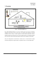
RSP-APE-030M User’s Manual 1. Overview Figure 1.1 RSP-APE-030M Repeater R-tron RSP-APE-030M Repeater can be used in CDMA service hole spots like in-buildings, underground and tunnels to cover its service area. This repeater system designed for dual and simultaneous service, namely, it receives signals from the base station through donor antenna, amplifies the signals and re-transmits it to one or other mobile terminals.
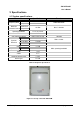
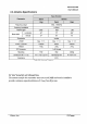
RSP-APE-030M User’s Manual 2. Specifications 2.1 System specifications Parameter Frequency Band Specifications Down Link 1930 ~ 1995 MHz Up Link 1850 ~ 1915 MHz Maximum Down Link Transmit Power Up Link 5 or 10 or 15 MHz Gain 70dB Gain Adjustment Range 30dB in steps of 1dB Emissions ±885 kHz < -45 dBc ±1.98 MHz < -50 dBc ± 2.25 MHz < -13 dBm Ripple Freq. Selectivity 65MHz Bandwidth +15 dBm Operating Bandwidth Spurious Remark Max.
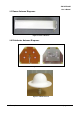
RSP-APE-030M User’s Manual 2.3 Donor Antenna Diagrams Figure 2.2 Donor Antenna 2.4 Distributor Antenna Diagrams Figure 2.3 Patch Antenna Figure 2.4 Omni Antenna R-tron., Inc.
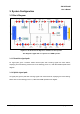
RSP-APE-030M User’s Manual 3. System Configuration 3.1 Block Diagram Figure 3.1 shows the block diagram of a band Selective repeater. This diagram is applicable to repeaters for CDMA systems. 3.1.1 Downlink signal path DL signal path gives a wireless mobile terminal path after receiving signal from base station, amplifying and noise filtering. Please refer to the following picture 3.1, RSP-APE-030M repeater block diagram. 3.1.
RSP-APE-030M User’s Manual 4. Installation 4.1 Installation Overview The following gives you guide how you can install R-tron repeater properly, considering field situation and installation specific conditions. 4.2 Safety 4.2.1 Purpose The following information gives you how you can proceed your job correctly and eliminate dangerous condition. 4.2.2 Application Range Installation supervisor should check and do the proper thing to check preliminary dangerous condition. 4.3 Installation information-1 4.3.
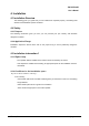
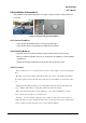
RSP-APE-030M User’s Manual 4.4 Installation Information-2 The installation of the repeater depends on the types of support, location, and the demand of the carrier. Figure 4.1 Antenna & Repeater Installation 4.4.1 General Condition - Check whether the repeater status is correctly horizontal angle. - Check whether there is enough space for maintenance and repair. 4.4.2 Installing Band set - Repeater main box should be installed 8.2 inches at least, above from the ground.
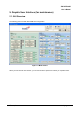
RSP-APE-030M User’s Manual 5. Graphic User Interface (for maintenance) 5.1. GUI Overview The following picture is RSP-APE-030M GUI Configuration. Figure 5.1 Main window When you first execute main window, you can see the above picture and it show you repeater status. R-tron., Inc.
RSP-APE-030M User’s Manual 5.2 Preliminary Steps for GUI Execution & Maintenance 5.2.1 Preliminary Steps before using GUI a. Check all connection status during the installation. b. Set the baud rate which you are going to use. c. Connect the repeater main power cable. d. Connect RSP-APE-030M “LOCAL OMT” with PC, using RS232 cable. Figure 5.2 Connection RSP-APE-030M with PC 5.2.2 Executing USB Driver & GUI program a. Excuting “PreInstaller” and check the USB driver is normal and the port number.
RSP-APE-030M User’s Manual 5.3 How to operate GUI & Functions Repeater can be controlled in Set-up mode. In Set-up pop-up window, you can input the value and control DL/UL HPA, AGC, Shutdown and attenuation. When you are going to check repeater status, click “Synchronize” button which is in the bottom side in the screen. After setting output value, you can set AGC/ASD level value, using AGC/ASD button. Figure 5.6 Setup mode R-tron., Inc.
RSP-APE-030M User’s Manual 5.3.1 Description for icon indication Figure 5.7 Main icons ▶ Polling : Communication possible ▶ Stop : Stop Communication ▶ File : Load the file of downloading ▶ Exit : Exit 5.3.2 How to set repeater gain System gain value can be changed using Down/Up link attenuation value control which is in “ATTN” pop-up window. Available set attenuation value is from 0 to 30 dB, Down/Up Link both. You can check current system gain in status mode. Figure 5.8 Gain Setting R-tron.
RSP-APE-030M User’s Manual 5.3.3 Circumstance Condition Control This function enables you to set the internal temperature of the system and the upper values of the input/output level. To change the values, you can enter the desired settings and click the “APPLY” button at the upper part of the control window. In the left side, you can see current settings for the internal temperature of the system. Figure 5.9 Control Window of Environmental Conditions 5.3.
RSP-APE-030M User’s Manual Figure 5.12 AGC/ASD Setting window R-tron., Inc.