
User Manual

NOTCHCELL 20W OPERATING MANUAL
R-tron America, Inc. Page: 50 / 57
Appendix A. System Parameters
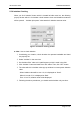
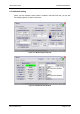
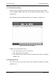
A.1 System state window
On the top side of GUI, repeater model name, current bandwidth and band are
displayed. On the left side, there are “SET MODE” and “STATUS MODE” buttons.
A.1.1 SYSTEM
System Address : Indicates where the repeater is installed.
System ID : Allocated number from base station. (from 0 to 16383)
For example, when PCS & A band system ID is 0, Service will be indicated as “PCS
B 0”.
RTC Time: Display current time which currently set in MCU.
When repeater time is incorrect, you can change it correctly, using Time Set in the
menu bar.
Repeater Capacitor : Repeater output
Repeater Version : H/W version
S/W Version : Repeater program(firmware) version
Type : Repeater type
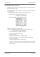
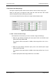
A.1.2 ATTNUATION
DL / UL ATTN : On “SET Mode”, user can set downlink & uplink path attenuation.
DL / UL GAIN : On “STATUS Mode”, user can check DL/UL attenuation system
gain which is set on “SET Mode”
A.1.3 ENVIRONMENT
Env. Temp. : It displays system temperature.
DC Volt : It displays voltage status of power supply unit.
Current : It displays using system current volume
Battery Volt : It displays voltage status of power supply unit