
User Manual

NOTCHCELL 20W OPERATING MANUAL
R-tron America, Inc. Page: 46 / 57
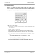
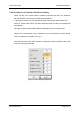
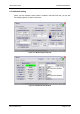
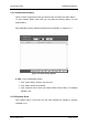
5.5.9 How to Set Alarm Range
Set input / output RF power maximum and minimum value of Down Link/Up Link.
When you are going to change the value, input the value and click “SET” button
which is located in up side control pop-up window.
You can check down link and up link input / output values at status mode.
Figure 5.16 Controlling Input/output
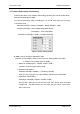
► Note : How to set Alarm range
* We would like to recommend you how to set alarm range as followings,.
① Make the gap between downlink path input power value and downlink input
power alarm range will be 5dB.
For example, when input power is -50dBm, alarm range will be from -55 to -
45dBm.
② Make the gap between downlink output power and downlink path output
power value will be 3dB.
For example, when output power is 30dBm, alarm range will be from 27 to 33
dBm.
③ Uplink output power alarm range will be from 0 to 30 dBm.