
User Manual

NOTCHCELL 20W OPERATING MANUAL
R-tron America, Inc. Page: 42 / 57
5.5.7 Gain & Attenuation Value Setting
Following the above 5.5.6 isolation value setting, repeater gain can be set like below.
Maximum repeater gain is 95dB.
You can set attenuation value, controlling DL / UL ATTN. value which you are going
to be output value.
- Maxi mum Gain(dB) = Isolation Value(dB) – Margin (Margin ≥ 15dB)
- Repeater Gain(dB) = User’s targeting Repeater Output
Power(dBm) - Input power(dBm)
- Attenuation Value(dB) = 95(dB) – Repeater Gain(dB)
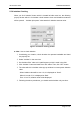
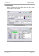
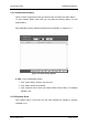
Figure 5.14 Gain setting window
► Note : How to set gain & attenuation value
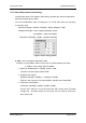
Example 1) Field isolation value is 100. Down Link Path repeater input value
is -55dBm. User’s target output is 30dBm.
① Maximum available gain = 100(dB)–15(dB) = 85dB
Therefore, maximum gain value is 85dB.
② Repeater Gain setting :
Repeater Gain(dB) = 30(dBm) – (-55(dBm)) = 85(dB)
When an user is going to use output 30dBm, repeater gain needs 85dB.
③ Attenuation Value setting :
Attenuation Value(dB) = 95(dB) – 85(dB) =10(dB)
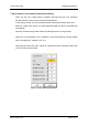
Set “DL Attn” value as 10 in the GUI and click “SET” button which is located
up-right end. On status mode, you can check “DL Attn” value is 10 and “DL
Gain” value is 85.