
User Manual

NOTCHCELL 20W OPERATING MANUAL
R-tron America, Inc. Page: 29 / 57
4. Operation
4.1 Isolation test procedure of Antenna
4.1.1 Isolation Measurement using for Signal Generator and Spectrum Analyzer.
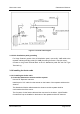
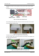
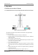
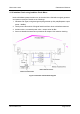
Figure 4.1 Isolation test with S/G & S/A
The followings are isolation check procedures on the field site, using signal analyzer
and spectrum generator.
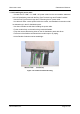
a Set-up the equipment as shown in Figure 4.1 Isolation test
b Set up the analyzer for the highest possible sensitivity (more than –100dBm) for
0 dBm source-power.
c Set the analyzer to “peak search mode “.
d After calibrated cable loss between Measurement Equip and Antenna, set the
output-power of the generator to 0 dBm.
e Turn on Signal Generator Output
f Measure the Antenna Isolation, using spectrum analyzer. The minimum isolation
is the highest value of the curve (excepting carriers transmitted by surrounding
BS).
g Change measurement-ports to check for the opposite direction by repeating the
measurement procedure.
h Repeat the test for the opposite path of the repeater. Step a to g.
*Isolation per carrier frequency is worse value.