Notchcell 20W Operating Manual Programmable Type Version 1.
NOTCHCELL 20W OPERATING MANUAL CONTENT 1. OVERVIEW 3 2. SPECIFICATIONS 4 2.1 NOTCHCELL 20W 4 2.2 ANTENNA 5 3. INSTALLATION 6 3.1 GENERAL 6 3.2 TECHNICAL SPECIFICATION 7 3.3 INSTALLING INFORMATION 11 4. OPERATION 29 4.1 ISOLATION TEST POCEDURE OF ANTENNA 29 5. GRAPHIC USER INTERFACE 31 5.1 INTRODUCTION 31 5.2 GETTING STARTED 32 5.3 CONNECTING TO THE NOTCHCELL 33 5.4 SETUP & STATUS MODE SYSTEM DISPLAY 35 5.5 REPEATER SET USING GUI 37 APPENDIX A. SYSTEM PARAMETERS 49 A.
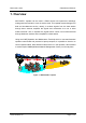
NOTCHCELL 20W OPERATING MANUAL 1. Overview NOTCHCELL repeater can be used in CDMA service hole spots like in-buildings, underground and tunnels to cover its service area. This repeater system designed for dual and simultaneous service, namely, it receives signals from the base station through donor antenna, amplifies the signals and re-transmits it to one or other mobile terminals.
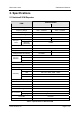
NOTCHCELL 20W OPERATING MANUAL 2. Specifications 2.1 Notchcell 20W Repeater SPECIFICATION ITEM DOWN-LINK Repeater Type UP-LINK Band Selective (5,10,15,20,5+5,10+5,15+5MHz) Frequency Range 1930 ~ 1990MHz 1850 ~ 1910MHz CDMA Frequency Error < ± 0.05ppm Rho (Pilot Only) > 0.
NOTCHCELL 20W OPERATING MANUAL 3. Installation 3.1 General 3.1.1 Overview This standard provides a reasonable and efficient installation method for the RF repeater in consideration of site conditions and particularity of the installation process. 3.1.2 Structure - Technical details: Description on the configuration and standard for the main box. - Installation of cabinet: Description on the installation method of main box and PSU (Power Supply Unit) box.
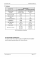
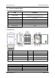
NOTCHCELL 20W OPERATING MANUAL 3.2 Technical specification 3.2.1 Environmental Conditions ITEM STANDARD Power supply 110Vac ± 20% / 50/60Hz ±5% or +24Vdc battery backup available (option) Operating temperature - 30 ~ +50 ℃ Humidity 95 % Consumption power 400W(Normal) / 700W(Max.) Rainfall 100 mm/Hr Water proof NEMA 4x Wind pressure 60m/s 3.2.2 Mechanical specification 3.2.2.1 Main box NO. Title NO.
NOTCHCELL 20W OPERATING MANUAL 3.2.2.2 PSU box NO. Title NO. Title 1 Name Plate 3 Heat Sink 2 Base 4 MTG Bracket Figure3.2 PSU box ITEM SPECIFICATION Size (W x H x D) 450 X 385 X 315 mm / 17.72 X 15.16 X 12.40 inch Weight Less than 25Kg / Less than 55lbs R-tron America, Inc.
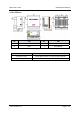
NOTCHCELL 20W OPERATING MANUAL 3.2.2.3 Donor antenna Figure3.3 Donor antenna ITEM SPECIFICATION RF Connector 1 X 7/16-female Size (W x H x D) Antenna 1020 X 675 X 116 mm / 40.16 X 26.57 X 4.57 inch Shipping box 1130 X 785 X 270 mm / 44.49 X 30.91 X 10.63 inch Weight R-tron America, Inc.
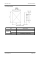
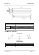
NOTCHCELL 20W OPERATING MANUAL 3.2.2.4 Distributor antenna Figure3.4 Distributor antenna ITEM SPECIFICATION RF Connector 1 X 7/16-female Size (W x H x D) Antenna 1500 x 300 x 110 mm / 59.06 X 11.81 X 4.33 Shipping box 1560 x 320 x 190 mm / 61.47 X 12.60 X 7.48 Weight Less than 10 kg / Less than 22 lbs 3.2.2.5 Mount Pole (Option Item) F igure3. 5 Mount pole ITEM SPECIFICATION Length 2500 mm or 2900 mm / 98.43 or 114.17 inch Weight Less than 6 kg / Less than 13.
NOTCHCELL 20W OPERATING MANUAL 3.3 Installing information 3.3.1 Installation site 3.3.1.1 Right-of-way - The repeater shall be installed in the location owned or leased by the carrier. - If the repeater is installed on the roof, spaces for the installation must be considered. 3.3.1.2 Conditions for the Installation space Installation of the repeater requires the following spaces. 1) Roof Do not install the repeater near heavy equipments or water tanks for load distribution.
NOTCHCELL 20W OPERATING MANUAL 3.3.1.4 Carrying and loading Be careful not to cause any accident when loading the cabinet or carrying it to the installation site and not to be damaged when handling it. To prevent corrosion, carry the cabinet in silver vinyl or a wooden box. Warning: To prevent all possible damage, do not unpack the box until the cabinet is carried to the installation location. Do not load excessive material on the top or cover of the packing. 3.3.
NOTCHCELL 20W OPERATING MANUAL 3.3.3 Installing the repeater The installation methods of the repeater vary depending on the types of support (steel tower), location, and demand of the carrier. This standard specifies the general supporting methods and is subject to the types of support. Figure3.6 Definition of assemblies (ex. electric pole) 3.3.3.1 General - Check the level of ground when installing the repeater. - Check if there is enough space for maintenance.
NOTCHCELL 20W OPERATING MANUAL 3.3.3.2 Installing band - When installing the repeater on a cylindrical support such as steel pipe and steel pole, manufacture and install the band in accordance with the size of the support. - When installing the repeater on the roof, the standard height to the bottom of the repeater shall be 1.2m. - Install the AC distribution panel near the repeater or in the rear of the repeater. Figure3.7 Band installation diagram 1 (steel tower type) R-tron America, Inc.
NOTCHCELL 20W OPERATING MANUAL Figure3.8 Band installation diagram 2 (electric pole type) R-tron America, Inc.
NOTCHCELL 20W OPERATING MANUAL Figure3.9 Band installation diagram 3 (location of repeater) Band Set Figure 3.10 Band set R-tron America, Inc.
NOTCHCELL 20W OPERATING MANUAL 3.3.3.3 Installing L-Type angle - The AC distribution panel shall be, in principle, on the left of the repeater. - When installing the repeater on the roof, the standard height to the bottom of the repeater shall be 1.2m, and 4m when on a field. Figure 3.11 L-Type installation diagram 1 (steel tower type) R-tron America, Inc.
NOTCHCELL 20W OPERATING MANUAL Figure 3.12 L-Type installation diagram 2 (location of repeater) R-tron America, Inc.
NOTCHCELL 20W OPERATING MANUAL Figure 3.13 L-Type installation diagram 3 (steel tower type) R-tron America, Inc.
NOTCHCELL 20W OPERATING MANUAL 3.3.4 Installing AC power cable 3.3.4.1 AC distribution panel Install the AC distribution panel on the steel tower to supply AC power to PSU of the repeater. 1) AC distribution panel specification The AC distribution panel consists of a Breaker (30A), a Surge-Protector (40KA), a two hole outlet, and terminal blocks. The cabinet shall be waterproof and equipped with cable bushings on the bottom. See “Chapter 3.3.3 Installing the repeater” to install the AC distribution panel.
NOTCHCELL 20W OPERATING MANUAL 3.3.4.2 Installing AC power cable - Connect the CV 5.5㎟ ~ CV 22㎟ x 2C power cable from the accumulative wattmeter to the AC distribution panel with the Ring Type Terminal Lugs and Flexible Conduits. - Use the Fork Type Terminal Lugs when connecting the AC power cable. - No cable will have contact points inside the conduit, and distribution/connection shall be allowed only in the AC distribution panel. - Use 22mm flexible conduit when installing the power cable.
NOTCHCELL 20W OPERATING MANUAL 3.3.5 Grounding Three types of grounding are applied - system grounding, arrester grounding, and steel tower grounding. The arrester and the fixing studs are installed on the bottom of the repeater. The steel tower grounding and arrester grounding shall be in conformity to the standard of the steel tower manufacturer. 3.3.5.1 General - Use the GV cable for the grounding. - Branch point shall be finished with C-tap and the heat shrink tube.
NOTCHCELL 20W OPERATING MANUAL Figure 3.17 Ground Cable Diagram 3.3.5.3 AC distribution panel grounding For Surge Protector ground of the AC distribution panel, connect GV 14㎟ cable to the repeater cabinet grounding cable (GV 38㎟), branching it off with C-Tap (38-14mm). Connect to the ground Terminal Block in the AC distribution panel with the Fork Type Terminal Lug. 3.3.6 Installing the feeder cable 3.3.6.
NOTCHCELL 20W OPERATING MANUAL 2) Connecting the feeder cable connector Figure 3.18 1/2”Feeder Cable Diagram ITEM Connector Feeder Cable Weight ARRESTER 1/2” F CABLE ANTENNA Type N - Female N - Male N - Male N - Female Quantity - 2 2 - Type - 1/2” F Cable - Quantity - 2` - 3) Cautions in the installation of the feeder cable Install the cable in the shortest distance, if possible, between the Antenna and the repeater.
NOTCHCELL 20W OPERATING MANUAL 4) Installing/ tying the feeder cable The installation of the feeder cable is sensitive to the bend radius and humidity. Therefore, the following regulations shall be observed. Maintain the minimum bend radius. (Higher than the standard presented by the manufacturers) The cable must not be entangled. Do not apply excessive force to the feeder cable to prevent bent insulated conductors or dug coverings. The outer connecting part of the connector must be waterproof.
NOTCHCELL 20W OPERATING MANUAL Assemble the Conduit End Cap (repeater accessory) at both ends of 36mm Flexible Conduit. Insert the assembled 1/2” feeder cable (shield cable) into the 36mm Flexible Conduit. Figure 3.20 Feeder Cable at Repeater Side After installing and tying the cable, connect the connector to the bottom of the antenna and then apply the Conduit End Cap. Figure 3.21 Connector on the Antenna Side Compress the Shield cable on the repeater with the heat shrink tube.
NOTCHCELL 20W OPERATING MANUAL 3.3.7 Installing Antenna 3.3.7.1 Precautions Antenna is a precise material. Make sure of no damage or deformation on it through the careful installation. Do not apply excessive force nor work in a hurry. The retainers shall be zinc plated. Set the accurate direction of the antenna with the transit when setting up antenna support and its installation direction.
NOTCHCELL 20W OPERATING MANUAL Figure 3.23 Antenna Installation R-tron America, Inc.
NOTCHCELL 20W OPERATING MANUAL 4. Operation 4.1 Isolation test procedure of Antenna 4.1.1 Isolation Measurement using for Signal Generator and Spectrum Analyzer. Figure 4.1 Isolation test with S/G & S/A The followings are isolation check procedures on the field site, using signal analyzer and spectrum generator. a Set-up the equipment as shown in Figure 4.1 Isolation test b Set up the analyzer for the highest possible sensitivity (more than –100dBm) for 0 dBm source-power.
NOTCHCELL 20W OPERATING MANUAL 4.1.2 Isolation Check using Isolation Check Menu Notchcell 20Watt repeater isolation can be checked in the field without signal generator and spectrum analyzer. Details are as followings. 1. Generate CW signal, using band guard pilot generator up link path(Repeater output power : 30dBm) 2. Check power value which CW signal feeds back from donor to distributor antenna. 3. Isolation value = measured power value + output value 30 dBm 4.
NOTCHCELL 20W O PERATING M ANUAL 5. Graphic User Interface 5.1 Introduction This standards provides you how to install Notchcell 20Watts repeater software which is programmable type and how to maintain it. 5.1.1 Compatibility Notchcell programmable type GUI(Graphic User Interface) can be used regardless of output power. GUI program is based on windows 2000 or XP and the version of software and firmware is as following,. Product Software version Firmware version NOTCHCELL 20W 1.1.0 1.1.1.
NOTCHCELL 20W O PERATING M ANUAL 5.2 Getting Started 5.2.1 Necessities . GUI software program Computer RS232 cable for Notchcell and PC connection 5.2.2 System Requirements Windows 2000/XP Free serial port or USB to RS232 converter 128 MB RAM 10 MB free space on hard drive Pentium III processor monitor (minimum 1024 X 768) Mouse, keyboard CD-ROM drive 5.2.3 Software Installation - To install GUI 1. Click “setup.exe” file which is in GUI program folder and then install GUI program.
NOTCHCELL 20W OPERATING MANUAL 5.3 Connecting to the NOTCHCELL 5.3.1 Local Connection How to setup a connection directly (local) to the Notchcell. 1. Connect RS232C cable with Notchcell “LOCAL OMT” port. 2. Connect adapter with PC serial port. When it comes to USB, use USB to RS232C adapter. Figure 5.2 Local connection 5.3.2 AC Power ON 1. Check the status of Notchcell power cable connection. Figure 5.3 AC Power cable connection R-tron America, Inc.
NOTCHCELL 20W OPERATING MANUAL 2. Open PSU box door and AC input switch as “ON” status. Figure 5.4 AC Power ON 3. Check whether AC and DC fail LED color which is located in power supply unit will be green or not. Figure 5.5 Power Alarm LED ► Note : “BATT. FAIL” color will be green when battery properly connected with “DC IN(24V)” and power supply unit “EXT. BATT. Input” switch should be “ON” status. R-tron America, Inc.
NOTCHCELL 20W O PERATING M ANUAL 5.4 Setup & Status Mode System Displays Notchcell GUI consists of “Setup Mode” which enables system control and “Status Mode” which indicates system status. More details about GUI parameter, check Appendix A – System Parameters. 5.4.1 Setup Mode Repeater can be controlled in Setup mode. In Setup pop-up window, you can input the value and control Bandwidth/Band, DL/UL Path, ALC, Shut down and attenuation.
NOTCHCELL 20W O PERATING M ANUAL 5.4.2 Status Mode When you are going to check repeater status, click “Status mode” button which is in the up-right side in the screen. And then check the value which is displayed in “Status mode” and you can change output value, using attenuation value. Figure 5.7 Status mode window R-tron America, Inc.
NOTCHCELL 20W OPERATING MANUAL 5.5 Repeater Set Using GUI 5.5.1 Executing GUI program Execute Notchcell GUI program. (Installation details are in Chapter 5.2.3) Figure 5.8 Execute GUI on Windows XP 5.5.2 User Check When you execute GUI program, you can see login pop-up window. (ID : operator / Password : spcs) Figure 5.9 login pop-up window R-tron America, Inc.
NOTCHCELL 20W OPERATING MANUAL 5.5.3 Communication Port and Speed Configuration You should set the communication speed and port between your computer and Notchcell for mutual communication. User can set communication speed and port which control button is located upper left-side in the main window screen. After that, communication is started. (Communication Speed : 38,400 bit / second) Figure 5.10 Communication Port and Speed Configuration ► Note : How to check computer communication port 1.
NOTCHCELL 20W OPERATING MANUAL 5.5.5 Bandwidth & Band Setting When you click “Bandwidth” which is located left end in main window menu bar, you can see bandwidth and band configuration pop-up window. Then, set the band and bandwidth, considering the field condition. (See the following table 5.
NOTCHCELL 20W OPERATING MANUAL ④ Click “SET” button to fix bandwidth and band. ⑤ Click “EXIT” button for exiting bandwidth pop-up window. R-tron America, Inc.
NOTCHCELL 20W OPERATING MANUAL 5.5.6 Isolation Checking When you click “Isolation” button which is located left side menu bar, the following pop-up window which is for isolation check between donor and distributor antennas will be opened. “Isolation pilot power” value stands for isolation antenna value. Figure 5.13 Isolation checking window ► Note : How to check isolation. ① Considering your location, check whether the repeater bandwidth and band are properly set. ② Select “Isolation” in the menu bar.
NOTCHCELL 20W OPERATING MANUAL 5.5.7 Gain & Attenuation Value Setting Following the above 5.5.6 isolation value setting, repeater gain can be set like below. Maximum repeater gain is 95dB. You can set attenuation value, controlling DL / UL ATTN. value which you are going to be output value. - Maxi mum Gain(dB) = Isolation Value(dB) – Margin (Margin ≥ 15dB) - Repeater Gain(dB) = User’s targeting Repeater Output Power(dBm) - Input power(dBm) - Attenuation Value(dB) = 95(dB) – Repeater Gain(dB) Figure 5.
NOTCHCELL 20W OPERATING MANUAL Example 2) Field isolation value is 100. Repeater input value is -65 dBm. User’s target output is 30dBm. ① Maximum available gain = 100(dB)–15(dB) = 85dB ② Repeater Gain setting : Repeater Gain(dB) = 30(dBm) – (-65(dBm)) = 95(dB) Current input level -65dBm. Therefore, when an user is going to use output; 30dBm, repeater gain needs 95dB. Considering maximum repeater gain;85dB, you can not set 30dBm as repeater output value.
NOTCHCELL 20W OPERATING MANUAL 5.5.8 ALC(Auto Level control) & Shut-Down Setting When you click “ALC” button which is located in left side menu bar, ALC, shutdown set and ON/OFF control pop-up window will be displayed. In the pop-up window, you can set downlink path output power like the above 5.5.7. When DL output value will be over than shutdown target set value, the repeater will be shutdown. Normally, shutdown target value will be set 3dB higher than ALC target value.
NOTCHCELL 20W OPERATING MANUAL ► Note : How to set ALC / Shutdown Target Value. ① When user set downlink path output power is 40dBm : About ALC, DL output power value is 40dBm. Therefore, set ALC target value as 40. ② Normal field situation, shutdown target value will be 43, 3dB higher than ALC target value. ► Note : How to work ALC and ASD If the ALC gets activated with system output exceeding ALC Target values, you need to use the USER ATT to adjust the output to meet the range of the upper settings.
NOTCHCELL 20W OPERATING MANUAL 5.5.9 How to Set Alarm Range Set input / output RF power maximum and minimum value of Down Link/Up Link. When you are going to change the value, input the value and click “SET” button which is located in up side control pop-up window. You can check down link and up link input / output values at status mode. Figure 5.16 Controlling Input/output ► Note : How to set Alarm range * We would like to recommend you how to set alarm range as followings,.
NOTCHCELL 20W OPERATING MANUAL 5.5.10 Modem Setting When you click “Modem” button which is located in left side menu bar, you can see the following picture for basic modem set. Figure 5.17 Modem System Window Figure 5.18 Modem Status Window R-tron America, Inc.
NOTCHCELL 20W OPERATING MANUAL ► Note : How to check whether wireless modem properly works. ① Click “Modem” which is located in left side menu bar. ② When you see pop-up window like figure 5.17, make communication port configuration same as GUI setting. ③ Click “START” button. ④ Check every parameters are same as your target value.(You can see more details at appendix B B1.
NOTCHCELL 20W OPERATING MANUAL 5.5.11 Default Alarm History When an alarm is happened, alarm type and time are recorded in the alarm history. To save repeater status check time, you can delete all alarming history for next default setting. More detail alarm history window parameters are in appendix A, Chapter A.2.1. Figure 5.19 Alarm History Window ► Note : How to delete alarm history ① Click “Alarm History” button in the menu bar. ② Click “Reset” button for all deletes.
NOTCHCELL 20W OPERATING MANUAL Appendix A. System Parameters A.1 System state window On the top side of GUI, repeater model name, current bandwidth and band are displayed. On the left side, there are “SET MODE” and “STATUS MODE” buttons. A.1.1 SYSTEM System Address : Indicates where the repeater is installed. System ID : Allocated number from base station. (from 0 to 16383) For example, when PCS & A band system ID is 0, Service will be indicated as “PCS B 0”.
NOTCHCELL 20W OPERATING MANUAL A.1.4 ON / OFF DL / UL HPA : Downlink and uplink power amplifiers ON / OFF. Battery : Battery ON / OFF(Battery is optional) A.1.5 POWER DL In Power : Set alarm range and display downlink path input power. DL Out Power : Set alarm range and display downlink path output power. UL Out Power : Set alarm range and display uplink path output power. A.1.6 STAUS (ON / OFF) DL / UL Path : It displays the status of system DL/UL path.
NOTCHCELL 20W OPERATING MANUAL A.1.7 ALARM DC / AC Alarm : Appears when DC/AC voltage exceeds the upper/lower values set in the “ENVIRONMENT” window. Door alarm: Appears when the housing door of the repeater is open. Battery Fail Alarm: This alarm stays unseen in the alarm indication window until you turns the battery on in the “ON/OFF” window. This alarm appears when the battery voltage values exceed the upper/lower values set in the “ENVIRONMENT” window.
NOTCHCELL 20W OPERATING MANUAL A.2 Menu Selection Window A.2.1 Alarm History This window shows details on alarms stored in the system. Total Alarm Count : Indicates the number of alarms stored in the current MCU. Each count refers to alarm(s) occurring in the same timeframe. The number can be up to 250. Listing Alarm Index : Lets you set the number of alarms seen on the screen. When you set a desired number and press the ‘listing’ button, the screen will show related alarms.
NOTCHCELL 20W OPERATING MANUAL A.2.4 ALC (Auto Level Control) This function lets you control ALC settings and the ON/OFF status. To change a setting, you need to enter a value and click the SET button at the lower part of the Control Window. ALC Target : DL output value which you are going to maintain. Shutdown Target : When repeater DL output value will be over than initial set value, the repeater will be shutdown. Shutdown Count : Set the number of shutdown times.
NOTCHCELL 20W OPERATING MANUAL A.2.7 Download When the firmware is upgraded, you can download a new firmware program to the MCU. Downloaded files should be in Binary code. ►Note : How to do firmware download ① When you click the Download at the menu window. ② Click the File to open in the Download window. ③ Click a file to be upgraded. ④ If a desired file is selected in the “File Path Name”, you can press the Start button for upgrade.
NOTCHCELL 20W OPERATING MANUAL Appendix B. Modem B.1 System Window B.1.1 General Control Communication Port : Connects MCU to the modem port. Modem Own Number : Refers to the modem number, with which you can call using a modem. Firmware Version : Refers to the version of currently used software. B.1.2 WNMC Configuration Cascade Code : Refers to the ID designated by operator where the repeater is installed. The ID is composed of ten-digit characters and figures.
NOTCHCELL 20W OPERATING MANUAL B.1.4 Modem Configuration Network Connection : ① Modem Mode : This button lets you see the modem status. When you press the button, the Modem Status window, the Modem Configuration window, the Modem Statistics window, and the Modem Status window are activated. With the [NMST] button in the Modem Status window, you can see modem status. ② PPP Mode : Stands for Point to Point Protocol, which helps set connection between the MCU and WNMC. PPP connection is automatically set.
NOTCHCELL 20W OPERATING MANUAL B.2 Modem Window B.2.1 Modem Status NMST Button : Refers to AT command to report current modem status with AT + NMST commands programmed in the button. When you press the button, modem status information is displayed. Analog / Digital : Shows transferring methods of the modem (Analog/digital types). When the modem uses analog communication method, ‘Analog’ is displayed; if it uses Digital communication method, ‘Digital’ is displayed.
NOTCHCELL 20W Repeater Operating Manual Copyright © 2006 R-tron America, Inc. All Rights Reserved 10977 Granada Lane, Suite #225 Overland Park, KS 66212 Any reproduction, distribution, or revision of any or all portions of this manual is prohibited without written permission from R-tron America, Inc. The information in this guide is subject to change without any prior notification. www.r-tron.