Notice Trademark R-tron is a registered trademark of R-tron Inc. Other products and company names mentioned here in this manual might be trademarks or trade names of their respective owners. Copyright Copyright © R-tron Inc. 2000-2008 All Rights Reserved Any reproduction, distribution, or revisions of any or all portions of this manual is prohibited without written permission from R-tron Inc. Notice This document describes the specifications, installation, and operation of the Tri MINI.
Safety Precautions Opening the Tri MINI could result in electric shock and may cause severe injury. Warning Connect the equipment frame ground to building ground. Warning Operating the Tri MINI with antennas in very close proximity facing each other could lead to severe damage to the repeater. Safety Precautions Warning Caution RF EXPOSURE INFORMATION A minimum separation distance of 7.
Contents Glossary 3 1. Introduction 4 2. Description 6 2.1 Main Unit Overview 6 2.2 Sub Unit Overview 7 2.2.1 Block Diagrams 2.2.2 PSU (Power Supply Unit) 9 2.2.3 UDCs (Up Down Converter) 10 2.2.4 MCU (Main Control Unit) 11 2.2.5 HPAs (High Power Amplifiers) 12 2.2.6 Multiplexer 13 3. Hardware Installation 14 3.1 Check List of Items 14 3.1.1 Items 14 3.2 Mounting 15 3.3 Grounding 18 3.4 RF Cable Connection 18 3.5 Power On 20 4. Operation 8 21 4.1 Connections 21 4.
Glossary The following is a list of abbreviations and terms used in this manual.
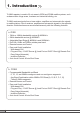
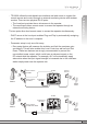
1. Introduction Tri MINI repeater is used to fill out areas in iDEN and CDMA mobile systems, such as base station fringe areas, business and industrial building, etc. Tri MINI receives signals from a base station, amplifies and retransmits the signals to mobile stations. Also it receives, amplifies and retransmits signals in the opposite direction. Both directions are served simultaneously with the following features: a.
- DHCP server at the Local port enables Plug and Play by automatically assigning the IP address to the user’s computer. 1. Introduction - TRI MINI utilizes the web-based user interface and web server to support the remote access and control through an external monitoring device with wireless modem. There are two physical RJ-45 ports: • The Local port provides the on-site access to the repeater. • The remote port allows remote users to access the repeater through an external monitoring device.
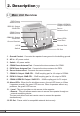
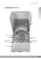
2. Description 2.1 Main Unit Overview iDEN Donor Antenna Port iDEN UL Output -30dB CPL CDMA Donor Antenna Port CDMA UL Output -30dB CPL Ground Contact AC IN Switch CDMA & iDEN DL Output -30dB CPL erver S Antenna Port Alarm LEDs Local Port Remote Port DC Out 1. Ground Contact : Connects the repeater frame ground to the building ground. 2. AC In : AC power socket. 3. Switch : AC power switch. 4. CDMA Donor Antenna Port : Connects the donor antenna for CDMA. 5.
2. Description 2.
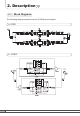
2. Description 2.2.1 Block Diagrams The following diagram explains how the Tri MINI serves signals. a. iDEN 800 DL PLL Donor antena Divider Attenuator 1 Band Pass Filter SAW Filter SAW Filter Band Pass Filter Attenuator 2 Is olator Band Pass Filter Is olator Digital Filter with Programmable options: RF switch RF switch RF switch RF switch Divider 851~869/851~868.8/851~868.6MHz and 862~869/862~868.8/862~868.6MHz for downlink. 806~824/806~823.8/806~823.6MHz and 817~824/817~823.8/817~823.
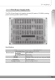
The PSU (Power Supply Unit) supplies a steady DC power to Tri MINI by drawing power from the general in-wall AC outlets. 2. Description 2.2.2 PSU (Power Supply Unit) Specifications Item Operating Temp Environmental Humidity Cooling method Voltage Current Frequency Leakage Current Specifications -10˚C~50˚C (14˚F~122˚F) 20%~90%RH Convection AC110~125V 13A Max / 6.5V, 1A / 12V, 1A / -12V, 4A / 27VDC 50~60Hz typical 0.5mA max.
2. Description 2.2.3 UDCs (Up Down Converters) The UDCs(Up Down Converters) are basically bi-directional amplifiers that sharply filters out unwanted noise. a. iDEN 800MHz Uplink Input Port Uplink Output Port 900MHz Uplink Input Port 900MHz Downlink Input Port Downlink Output Port 800MHz Downlink Input Port b.
The MCU (Main Control Unit) is the control unit of Tri MINI. It controls and monitors operational parameters. It is also responsible for generating an alarm, an event log and many other functions of the Tri MINI. J1 J2 2. Description 2.2.
2. Description 2.2.5 HPAs (High Power Amplifiers) The HPAs (High Power Amplifiers) amplifies the transmitted signal from a base station at the final stage of the repeater and vice versa. a. iDEN RF Input RF Output RF Output
A multiplexer is a device that combines two or more signals onto a common channel or medium to increase its transmission efficiency. CDMA & iDEN DL Output -30dB CPL Server Antenna Port Donor Antenna Port for iDEN iDEN 800 UL Input iDEN 900 UL Input iDEN UL Output -30dB CPL iDEN DL Output CDMA DL Output CDMA UL Output -30dB CPL 2. Description 2.2.
3. Hardware Installation The installation procedure is as follows: • Check List of Items • Mounting • Grounding • RF Cable Connection • Power On 3.1 Check List of Items Index 1 2 3 4 5 6 7 Items Repeater AC Cord Anchor Bolts Wall Mounting Template UTP Cross LAN Cable Quick Guide User’s Manual Quantity 1 1 4 1 1 1 1 3.1.
Tri MINI is easy to mount using the assembled mounting bracket, which has 9 holes for the provided 5/16” fixing screws. Step 1 Remove the cover of double-coated foam tape squares at each corner on the back side of the template. Step 2 Stick the provided template to the wall using the tape squares while adjusting the horizon. Mark the position for 4 screws depending on the installation location. Step 3 Drill holes directly through the template. User’s Manual 3. Hardware Installation 3.
3. Hardware Installation 16 Step 4 Install the set anchor bolts or the plastic anchor bolts on the holes. Step 5 Attach the mounting bracket to the wall using provided bolts or extra screws.
Lean the Tri MINI to hang the topside of the Guide Ring on the mounting bracket, and push toward the wall to mount. Step 7 Fix the Tri MINI using 8 screws provided. User’s Manual 3.
3. Hardware Installation 3.3 Grounding A rod on the left side is intended for a building ground. Connect the ground cable to the rod. Warning Dangerously high voltages may occur and damage the equipment if the equipment is not grounded properly. 3.4 RF Cable Connection Step 1 Connect a cable from a donor antenna to the DONOR ANTENNA Port. Step 2 Connect a cable from a repeater’s service antenna to the SERVER ANTENNA Port.
Enough isolation? Antenna isolation = Path loss between the server antenna port and the donor antenna port Antenna isolation Repeater max. gain +15dB If antenna isolation < Repeater max. gain +15dB → System oscillation or Low gain Model Max Gain RSN-TRI-25/24-DC 40dB to 80dB(CDMA) ≥95dB(80dB+15dB) 50dB to 80dB(iDEN) Tri MINI Donor antenna for iDEN Base Station Minimum required isolation (@Max Gain) Donor antenna for CDMA 3.
3. Hardware Installation 3.5 Power On 20 Step 1 Connect the power cord. Step 2 Plug the power cord into a wall outlet. Step 3 Power Switch turns on. Step 4 Check if the green LED at the bottom turns on.
4. Operation 3. Hardware Installation 4.1 Connections The remote port allows remote users to access the repeater through an external monitoring device. Power on the switch to “I” The switch is located on the bottom of the main body. Connect UTP Cross LAN Cable to a PC and the Tri MINI. Local port provides on-site access to the repeater.
4. Operation 4.2 System Requirements Tri MINI operates on a customer provided PC based platform with the following system requirements : • Windows® 2000, Windows® XP or Windows® Vista • Internet Explorer 6.0(Recommended) or higher • 128 MB RAM or higher • Pentium Ⅲ processor or higher • RJ-45 jack required 4.3 Network Setup 4.3.1 Windows XP Step 1 22 Click the Start button and My Network Places.
Click View network connections. Step 3 Right-click Local Area Connection to see a shortcut menu and click Properties. 4.