4.
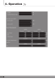
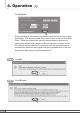
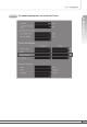
Alarms 4. Operation < Alarm Status > < Alarm Range > •R eported to Sprint : If an alarm occurs, the repeater will report directly to Sprint as a SNMP Trap so the LED of ALARM on the repeater does not blink. • On Site Alarm : If an alarm occurs, the alarm LED on the repeater will turn on. Please refer to the troubleshooting section of this manual. • No change of the values in the alarm range is recommended.
4. Operation b. CDMA Check CDMA in the left menu.
Step 1 4. Operation Solution 1. Easy Setup [Recommended] Return To Factory Defaults • To reset to factory defaults, click INITIALIZE. • To restore the previous settings, click RESTORE. Step 2 Select Bandwidth and Band and click APPLY. Step 3 Easy Setup Easy Setup proceeds to: • Isolation measurement On • Calculation of Available Maximum Gain by the isolation. • ASD On •A LC On to get Maximum DL Output Power 24dBm [Default] or Maximum Gain 80dB.
4. Operation Click Execute. Easy setup feature will measure the isolation and limit the maximum gain accordingly. This will also enable Auto Level Control as well as Auto Shut Down. These two features are strongly recommended to prevent the uncontrolled power output, which could have an adverse impact on the RF network and the repeater. For example, ALC will apply attenuation automatically when the input signal strength is increased due to the new base station deployment near the repeater site.
Setup will automatically begin. This process will take approximately 20 seconds. 4. Operation Step 6 10~20 seconds Click CDMA in the left menu.
4.
Maximum Gain 80dB if the DL Input Power < -56dBm. 4.
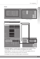
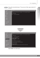
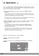
4. Operation After running Easy Setup or Isolation Measurement, Isolation value is displayed with “95” when the isolation is higher than 95dB, or it is displayed with the actual value when the isolation is lower than 95dB. • Automatic Level Control: Type under 24 and then click APPLY and ON. [Example] F or the repeater with 24dBm maximum output power, 80dB maximum gain/ 40dB gain control range, → If the signal -36dBm and the ALC is set as 24dBm, the gain will be 60dB to adjust to the output power.
Constant output power set as the ALC level. 4.
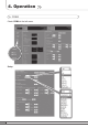
4. Operation Solution 3. Fixed Gain [Not Recommended] Step 1B Repeat step 1 through step 6. Easy Setup will calculate the Available Maximum Gain which defines the maximum gain to be setup. Warning Step 2B 58 DO NOT setup the gain higher than the Available Maximum Gain. Read DL Input Power and the gain controlled by Easy Setup.
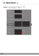
Turn off DL Amplifier and UL Amplifier. Step 4B ALC must be turned off; otherwise, the following message appears. Step 5B Change DL Gain and UL Gain. Warning Step 6B 4. Operation Step 3B The gain must be lower than the current value and Available Maximum Gain. Turn on DL Amplifier and UL Amplifier.
4. Operation Result DL and UL gain are fixed and the output power depends on the input power.
Uplink Gain Offset = -3dB 4. Operation Result ※ Restore Restore recovers the service by turning on the amplifiers of repeater fundamentally. After a permanent shutdown, the Restore turns on the amplifiers of the repeater with the period of Restore Interval.
4. Operation •R eported to Sprint : If an alarm occurs, the repeater will report directly to Sprint as a SNMP Trap so the LED of ALARM on the repeater does not blink. • On Site Alarm : If an alarm occurs, the alarm LED on the repeater will turn on. Please refer to the troubleshooting section of this manual. • No change of the values in the alarm range is recommended.
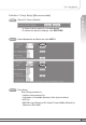
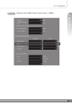
4. Operation 4.5.5 Upload Click Upload in the left menu. 4.5.5.1 Update: System Firmware Step 1 Click Browse. Step 2 A pop-up window will appear. Select the firmware file and click Open.
4. Operation 64 Step 3 Click UPDATE. Step 4 A pop-up window will appear after completing all the update processes. Click OK to reboot the system. Step 5 It will take a few minutes to update the new firmware. If the system reboots, go to the login page and login again. * Login page: http://192.168.0.1:83 (Local access) A specified IP address on DHCP(Remote access).
Step 1 Click Browse. Step 2 A pop-up window will appear. Select the GUI file and click Open. Step 3 Click UPDATE. 4. Operation 4.5.5.
4. Operation Step 4 pop-up window will appear after completing all the update processes. A Click OK to reboot the system. Step 5 It will take a few minutes to update the new Web GUI. If the system reboots, go to the login page and login again. * Login page: http://192.168.0.1:83 (Local access) A specified IP address on DHCP(Remote access). 4.5.5.3 Restore To restore the previous version, click RESTORE.
4. Operation 4.5.6 Reboot Click Reboot in the left menu. In this menu, you can reboot the system. 4.5.7 Alarm History Click Alarm History in the left menu. Click GET HISTORY, the history list of alarm issued will be displayed.
4. Operation To erase the alarm history on the memory, click ERASE HISTORY. A confirmation pop-up window will appear and click OK. To clear the alarm history on the screen, click CLEAR. Note Up to 300 alarm lists can be stored in the memory. 4.5.8 Logout If you want to logout, click Logout in the left menu. A warning pop-up window will appear and then click OK to logout.
5. Troubleshooting Problem Cause Solution No LED On Check the power cord for secure connection. Cannot communicate with the repeater. Check if the LAN cable is connected to the repeater and your computer, or your computer to set IP address. Or please disable and enable the Local Area Connection. The mobile phone is not working well. Turn on the power. Tri MINI Donor antenna for iDEN Base Station Donor antenna for CDMA 4.
5. Troubleshooting Problem Oscillation Cause Solution < a. iDEN > 1. The values above are changed randomly under operating of DL ALC, UL ALC, and ASD. 2. DL Amplifier and UL Amplifier are on and off iteratively. < b. CDMA > Turn off the repeater. Measure the isolation and verify if the isolation between the donor antenna and the server antenna is enough for the repeater. And then redo the easy set up or set up the repeater. 1.
Problem Cause Solution 5. Troubleshooting < a. iDEN > The red light turns on. On Site Alarms Range Lower Upper DL Input Power DL Output Power UL Output Power Temperature DC Voltage DC Current 14°F 20V 0A -30dBm 28dBm 28dBm 176°F 30V 7A < b. CDMA > Check if the value above is out of range.
6. Specifications RF Characteristics a. iDEN iDEN 800 Parameter Selectable Bandwidth DL DL & UL In-band BW:18MHz In-band BW:7.0MHz 18MHzbandwidth 851~869MHz 851~868.8MHz 851~868.6MHz 7MHzbandwidth 862~869MHz 862~868.8MHz 862~868.6MHz UL 18MHzbandwidth 806~824MHz 806~823.8MHz 806~823.6MHz 7MHzbandwidth 817~824MHz 817~823.8MHz 817~823.6MHz 896~901MHz 896~900.8MHz 896~900.
6. Specifications b. CDMA Specification Parameter Frequency DL 1930~1995MHz UL 1850~1915MHz Normal Input DL/UL Output Power Level 24dBm Gain 40dB ~ 80dB ± 2dB Attenuator -56dBm DL Range: 0~40dB Accuracy: ±0.7dB UL Range: 0~40dB Accuracy: ±0.7dB VVA ±3dB Min 29dB @±885KHz Spurious Remarks Min 39dB @±1.98MHz Min -13dBm@±2.25MHz Temperature Compensation Discontinuous 3FA / Continuous 7FA Roll Off Min 50dBc @±1MHz 5 / 10 / 15 / 20MHz-bandwidth, 5+5 / 10+5 / 15+5 / 20+5MHz, 5+5+5MHz.
6. Specifications Electrical & Environmental Specification Parameter Power supply Operating temperature Storage temperature Consumption power iDEN 800 iDEN 900 110V~125V AC, 60Hz typical *-10˚C~50˚C (14˚F~122˚F) -20˚C~60˚C (-4˚F~140˚F) ≤192.5W, (additional 24W) Mechanical Specifications Parameter RF connectors Size Weight Specification N-female x 3, SMA-female x 3 14.48 X16.73 X 11.37(Inch), 368 X 425 X 289(mm) 31.7kg (69.88lbs) The specifications are subject to change without any prior notification.
7. Appendix a. iDEN 6. Specifications The Operating Bandwidth and Frequencies of iDEN Mode Bandwidth Operating Frequency Downlink 18MHz-bandwidth Uplink iDEN 800 Downlink 7MHz-bandwidth Uplink Downlink iDEN 900 5MHz-bandwidth Uplink 851 ~ 869MHz 851 ~ 868.8MHz 851 ~ 868.6MHz 806 ~ 824MHz 806 ~ 823.8MHz 806 ~ 823.6MHz 862 ~ 869MHz 862 ~ 868.8MHz 862 ~ 868.6MHz 817 ~ 824MHz 817 ~ 823.8MHz 817 ~ 823.6MHz 935 ~ 940MHz 935 ~ 939.8MHz 935 ~ 939.6MHz 896 ~ 901MHz 896 ~ 900.8MHz 896 ~ 900.
7. Appendix b.
Operating Frequency 20+5 A1A2A3D+B2, A1A2A3D+B3, A1A2A3D+E, A1A2A3D+F, A1A2A3D+C3, A1A2A3D+C4, A1A2A3D+C5, A1A2A3D+G, A2A3DB1+B3, A2A3DB1+E, A2A3DB1+F, A2A3DB1+C3, A2A3DB1+C4, A2A3DB1+C5, A2A3DB1+G, A3DB1B2+E, A3DB1B2+F, A3DB1B2+C3, A3DB1B2+C4, A3DB1B2+C5, A3DB1B2+G, DB1B2B3+F, DB1B2B3+C3, DB1B2B3+C4, DB1B2B3+C5, DB1B2B3+G, B1B2B3E+C3, B1B2B3E+C4, B1B2B3E+C5, B1B2B3E+G, B2B3EF+C4, B2B3EF+C5, B2B3EF+G, B3EFC3+C5, B3EFC3+G, EFC4+G 5+5+5 A1+A3+B1, A1+A3+B2, A1+A3+B3, A1+A3+E, A1+A3+F, A1+A3+C3, A1+A3+C4, A
Warranty LIMITED WARRANTY This product, as supplied and distributed by R-tron, in the original carton, is warranted by R-tron against manufacturing defects in materials and workmanship for a limited warranty period of: Five (5) Year Parts and Labor This limited warranty begins on the original date of purchase, and is valid only on products purchased and used in the United States.
Return Material Authorization(RMA) Procedure The return and exchange of products are not allowed without prior approval from R-tron America, Inc. Please follow the exchange procedure below. 1. Call Tech Support for troubleshooting. 2. If the device has a hardware problem, R-tron will replace it if it is within warranty. A RMA number will be issued for the return. 3. R-tron will ship the replacement and a return label will be provided. 4.
MENO 80