
User's Manual Part 1

5
User’s Manual
2. Description
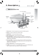
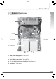
1. Ground rod : Connects repeater frame ground to building ground.
2. AC IN : AC Power socket and AC Power switch.
3. MODEM ANT : Connects the Modem antenna.
4. Donor Antenna Port : Connects the Donor antenna.
5.
UL Output
MON. : Displays the output of Up Link RF connected with a
measuring instrument and outputs 20dB lower than the actual output of RF.
(30dB lower for iDEN MINI)
6. DL Output MON.
: Displays the output of Down Link RF connected with a
measuring instrument and outputs 20dB lower than the actual output of RF.
(30dB lower for iDEN MINI)
7. Service Antenna Port : Connects the Service antenna.
8. ALARM
: When an alarm of the On Site Alarm occurs, the red LED blinks and
when it operates without any problem, the green LED blinks.
2. Description
2.1 Main Unit Overview
1. Ground rod
3. MODEM ANT
10. DC OUT
9. Mode
Selection
Jack
2. AC IN
4. Donor
Antenna
Port
8. ALARM
7. Service
Antenna
Port
5.
UL Output
MON.
6. DL Output MON.