RSN-iDEN-30-C User’s Manual
Address: R-tron Inc. 6402 College Boulevard Overland Park, KS 66211 Phone: +1-913-344-9977, 1-888-31R-TRON Fax: +1-913-344-9988 Internet: www.r-tron.
Notice Trademark R-tron is registered trademarks of R-tron Inc. Other products and company names mentioned herein this manual might be trademarks or trade names of their respective owners. Copyright Copyright © R-tron Inc. 2000-2007 All Rights Reserved Any reproduction, distribution, or revisions of any or all portions of this manual is prohibited without written permission from R-tron Inc. Notice This document describes the specifications, installation and operation of iDEN MINI.
Safety Precautions Opening the iDEN MINI could result in electric shock and may cause severe injury. Warning Connect the equipment frame ground to building ground. Warning Safety Precautions Warning Operating the iDEN MINI with antennas in very close proximity facing each other could lead to severe damage to the repeater. Caution RF EXPOSURE INFORMATION A minimum separation distance of 7.
Contents Glossary 3 1. Introduction 4 2. Description 5 2.1 Main Unit Overview 5 2.2 Sub Unit Overview 7 2.2.1 Block Diagram 8 2.2.2 PSU (Power Supply Unit) 8 2.2.3 UDC (Up Down Converter) 9 2.2.4 MCU (Main Control Unit) 10 2.2.5 HPAs (High Power Amplifiers) 11 2.2.6 Multiplexer 11 3. Hardware Installation 3.1 Check List of Items 12 3.2 Mounting 13 3.3 Grounding 15 3.4 RF Cable Connection 15 3.5 Power On 16 4. Operation 2 12 17 4.1 Connections 17 4.
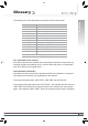
Glossary The following is a list of abbreviations and terms used in this manual.
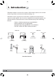
1. Introduction iDEN MINI repeater is used to fill out areas in iDEN mobile systems, such as base station fringe areas, business and industrial buildings, etc. iDEN MINI receives signals from a base station, amplifies and retransmits the signals to mobile stations. Also it receives, amplifies and retransmits signals in the opposite direction.
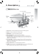
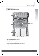
2. Description 5. UL Output MON. 6. DL Output MON. 7. Service Antenna Port 4. Donor Antenna Port 2. Description 2.1 Main Unit Overview 8. ALARM 9. Mode Selection Jack 2. AC IN 1. Ground rod 10. DC OUT 3. MODEM ANT 1. Ground rod : Connects repeater frame ground to building ground. 2. AC IN : AC Power socket and AC Power switch. 3. MODEM ANT : Connects the Modem antenna. 4. Donor Antenna Port : Connects the Donor antenna. 5. UL Output MON.
2. Description 9. Mode Selection Jack : The mode selection jack has two modes: Local Mode & Remote Mode. LOCAL Mode : This mode should be selected only if the iDEN MINI is used alone without being connected to a collocated repeater functioning as a local. (Use this mode for the Operation) REMOTE Mode : This mode should be selected if a repeater is being installed along with the iDEN MINI and the Ethernet port is being used for communicating with the repeater. 10.
2. Description 2.2 Sub Unit Overview 1. PSU 2. UDC 4. UL HPA 3. MCU 4. DL HPA 5. Multiplexer 1. PSU (Power Supply Unit) : See page 8. 2. UDC (Up Down Converter) : See page 9. 3. MCU (Main Control Unit) : See page 10. 4. UL / DL HPA (High Power Amplifiers) : See Page 11. 5. Multiplexer : See page 11.
2. Description 2.2.1 Block Diagram The following diagram explains how the iDEN MINI serves signals. SAW Filter with Programmable options 851~869 / 850.8~868.8 / 850.6~868.6 MHz with -65dBc@+-500KHz Donor antenna 18MHz-bandwidth Attenuator 1 Attenuator 2 7MHz-bandwidth SAW Filter with Programmable options 862~869 / 861.8~868.8 / 861.6~868.6 MHz with -65dBc@+-500KHz PLL 2 SAW Filter with Programmable options 935~940 / 934.8~939.8 / 934.6~939.
2. Description Specifications Item Operating Temp Humidity Cooling method Voltage Current Frequency Leakage Current Environmental Specifications Û&a Û& Û)a Û) 20%~90%RH Convection AC110~125V 6A Max / 6V, 12V, 27VDC 50~60Hz typical 0.5mA max.@110V AC 2.2.3 UDC (Up Down Converter) The UDC (Up Down Converter) is basically a bi-directional amplifier that sharply filters out unwanted noise.
2. Description 2.2.4 MCU (Main Control Unit) The MCU (Main Control Unit) is the control unit of iDEN MINI. It controls and monitors operational parameters. It is also responsible for generating an alarm, an event log and many other functions of the iDEN MINI.
The HPAs (High Power Amplifiers) amplifies the transmitted signal from a base station at the final stage of the repeater and vice versa. 2. Description 2.2.5 HPAs (High Power Amplifiers) 2.2.6 Multiplexer A multiplexer is a device that combines two or more signals onto a common channel or medium to increase its transmission efficiency.
3. Hardware Installation The installation procedure is as follows: • Check List of Items • Mounting • Grounding • RF Cable Connection • Power On 3.1 Check List of Items Index Items Quantity 1 2 3 4 5 6 7 Repeater AC Cord Anchor Bolts Wall Mounting Template UTP Cross LAN Cable Quick Guide User’s Manual 1 1 4 1 1 1 1 3.1.
iDEN MINI is easy to mount using the assembled mounting bracket, which has 9 holes for the provided 5/16” fixing screws. Step 1 Remove the cover of double-coated foam tape squares at each corner on the back side of the template. Step 2 Stick the provided template to the wall using the tape squares while adjusting the horizon. Step 3 Mark with a pen for the holes and drill the marks or drill holes directly on the mark in the template. User’s Manual 3. Hardware Installation 3.
3. Hardware Installation Step 4 Put the screws or bolts into the holes. Leave some space in order to hang the iDEN MINI on the 4 bolts. Step 5 Mount the iDEN MINI and tighten the bolts. Caution 14 Once equipment is mounted to the wall of the building, be sure to check that it is firmly secured.
3. Hardware Installation 3.3 Grounding A rod on the left side is intended for a building ground. Connect the ground cable to the rod. Warning Dangerously high voltages may occur and damage the equipment if the equipment is not grounded properly. 3.4 RF Cable Connection Step 1 Connect a cable from a donor antenna to the DONOR ANTENNA Port. Step 2 Connect a cable from a repeater’s service antenna to the SERVICE ANTENNA Port.
3. Hardware Installation Model Max Gain iDEN 30 80dB Minimum required isolation 95 (= 80+15) Donor antenna Repeater Service antenna Plugged in an AC outlet Base Station Mobile Station Donor Service 3.5 Power On 16 Step 1 Connect the power cord. Step 2 Plug the power cord into a wall outlet. Step 3 Power Switch turns on. Step 4 Check if the green LED at the bottom turns on.
4. Operation Repeater 1 DHCP Client Modem Hub 4. Operation 4.1 Connections DHCP Server Repeater 8 Base Station Monitoring Device with wireless modem for Remote Access DHCP Client When REMOTE port is in use, the repeater runs as a remote DHCP client. Power on the switch to “I” The switch is located on the bottom of the main body. Connect UTP Cross LAN Cable to a PC and the iDEN MINI. When LOCAL port is in use, the repeater runs as a local DHCP server.
4. Operation 4.2 System Requirements iDEN MINI operates on a customer provided PC based platform with the following system requirements : • Windows® 2000, Windows® XP or Windows® Vista • Internet Explorer 6.0(Recommended) or higher • 128 MB RAM or higher • Pentium 䳯 processor or higher • RJ-45 jack required 4.3 Network Setup 4.3.1 Windows XP Step 1 18 Click the Start button and My Network Places.
Click View network connections. Step 3 Right-click Local Area Connection to see a shortcut menu and click Properties. 4.
4. Operation 20 Step 4 Select Internet Protocol (TCP/IP) and click Properties. Step 5 Check Obtain an IP address automatically and click OK. Step 6 Close all windows.
Step 1 Click the Start button, point to Settings, and then click Network and Dial-up Connections. Step 2 Right-click Local Area Connection to see a shortcut menu and click Properties. User’s Manual 4. Operation 4.3.