
User's Manual Part 1

5
User’s Manual
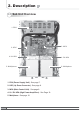
2. Description
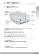
1. Ground rod: Connects the repeater frame ground to the building ground.
2. MODEM ANT : Connects the Modem antenna.
3. AC IN: AC Power socket and AC Power switch.
4. Donor Antenna Port: Connects the Donor antenna.
5.
UL Output -30dB CPL.
: -30dB coupling port for UL output.
6. DL Output
-30dB CPL.
: -30dB coupling port for DL output.
7. Server Antenna Port: Connects the Server antenna.
8. Alarm
: When the On Site Alarm occurs, the red LED turns on. When it operates
normally, the green LED turns on. When it operates without any problems, the
green LED turns on.
9.
• Local: This port provides on-site access to the repeater.
•
Remote: This port allows remote users to access the repeater through an
external monitoring device.
The two ports allow local and remote users to access the repeater
simultaneously.
10. DC OUT: Power outlet for compatible external devices only.
2. Description
2.1 Main Unit Overview
1. Ground
rod
10. DC OUT
3. AC IN
4. Donor
Antenna
Port
8. Alarm
7. Server
Antenna
Port
6. DL Output
-30dB CPL.
5. UL Output
-30dB CPL.
9. Local
Port
9. Remote
Port
2. MODEM
ANT