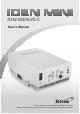
RSN-iDEN-25-C User’s Manual Please read this manual before operating this product. $IWHU \RX ¿ QLVK UHDGLQJ WKLV PDQXDO VWRUH LW LQ D VDIH SODFH IRU IXWXUH UHIHUHQFH
Address: R-tron Inc. 6402 College Boulevard Overland Park, KS 66211 Phone: +1-913-344-9977, 1-888-31R-TRON Fax: +1-913-344-9988 Internet: www.r-tron.
Notice Trademark R-tron is a registered trademark of R-tron Inc. Other products and company names mentioned here in this manual might be trademarks or trade names of their respective owners. Copyright Copyright © R-tron Inc. 2000-2008 All Rights Reserved Any reproduction, distribution, or revisions of any or all portions of this manual is prohibited without written permission from R-tron Inc. Notice This document describes the specifications, installation, and operation of the iDEN MINI.
Safety Precautions Opening the iDEN MINI could result in electric shock and may cause severe injury. Warning Connect the equipment frame ground to building ground. Warning Safety Precautions Warning Operating the iDEN MINI with antennas in very close proximity facing each other could lead to severe damage to the repeater. Caution RF EXPOSURE INFORMATION A minimum separation distance of 7.
Contents Glossary 3 1. Introduction 4 2. Description 5 2.1 Main Unit Overview 5 2.2 Sub Unit Overview 6 2.2.1 Block Diagram 7 2.2.2 PSU (Power Supply Unit) 7 2.2.3 UDC (Up Down Converter) 8 2.2.4 MCU (Main Control Unit) 9 2.2.5 HPAs (High Power Amplifiers) 10 2.2.6 Multiplexer 10 3. Hardware Installation 3.1 Check List of Items 11 3.2 Mounting 12 3.3 Grounding 15 3.4 RF Cable Connection 15 3.5 Power On 16 4. Operation 2 11 17 4.1 Connections 17 4.
Glossary The following is a list of abbreviations and terms used in this manual.
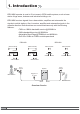
1. Introduction iDEN MINI repeater is used to fill out areas in iDEN mobile systems, such as base station fringe areas, business and industrial buildings, etc. iDEN MINI receives signals from a base station, amplifies and retransmits the signals to mobile stations. Also it receives, amplifies and retransmits signals in the opposite direction.
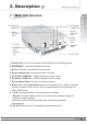
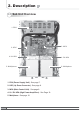
2. Description 5. UL Output -30dB CPL. 4. Donor Antenna Port 6. DL Output -30dB CPL. 7. Server Antenna Port 2. Description 2.1 Main Unit Overview 8. Alarm 9. Local Port 3. AC IN 2. MODEM ANT 1. Ground rod 9. Remote Port 10. DC OUT 1. Ground rod: Connects the repeater frame ground to the building ground. 2. MODEM ANT : Connects the Modem antenna. 3. AC IN: AC Power socket and AC Power switch. 4. Donor Antenna Port: Connects the Donor antenna. 5. UL Output -30dB CPL.
2. Description 2.2 Sub Unit Overview 1. PSU 2. UDC 4. UL HPA 5. Multiplexer 1. PSU (Power Supply Unit) : See page 7. 2. UDC (Up Down Converter) : See page 8. 3. MCU (Main Control Unit) : See page 9. 4. UL / DL HPA (High Power Amplifiers) : See Page 10. 5. Multiplexer : See page 10. 6 3. MCU 4. DL HPA 5.
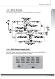
2. Description 2.2.1 Block Diagram The following diagram explains how the iDEN MINI serves signals. 2.2.2 PSU (Power Supply Unit) The PSU (Power Supply Unit) supplies a steady DC power to iDEN MINI by drawing power from the general in-wall AC outlets.