CAT-5 DAS TRI BAND (CDMA1900 / iDEN800 / iDEN900) User’s Manual Please read this manual before operating this product. After you finish reading this manual, store it in a safe place for future reference.
Notice Trademark R-tron is a registered trademark of R-tron Inc. Other products and company names mentioned here in this manual might be trademarks or trade names of their respective owners. Copyright Copyright © R-tron Inc. 2000-2010 All Rights Reserved Any reproduction, distribution, or revisions of any or all portions of this manual is prohibited without written permission from R-tron Inc. Notice This document describes the specifications, installation, and operation of the CAT-5 DAS.
Safety Precautions Opening the CAT-5 DAS equipment could result in electric shock and may cause severe injury. Connect the equipment frame ground to the building ground. Operating the CAT-5 DAS with antennas in very close proximity facing each other can lead to severe damage to the repeater. RF EXPOSURE INFORMATION A minimum separation distance of 7.9 inches (20cm) must be maintained between the user and the external antenna of the repeater to satisfy FCC RF exposure requirements.
Contents 1. Introduction............................................................................................................................................5 2. Description..............................................................................................................................................8 2.1 MHU Unit Overview….........……………….………………….………………………………….……………………….…………….………...8 2.1.1 MHU Internal Configuration…………………………………………………………………………………………………………..9 2.1.
4. Operation ......................................................................................................................................…….30 4.1 System Requirements…...…………………………...……..………………………….…………………………………………………………30 4.2 Network Setup…..……………………………………………..…………….………………………………………………………………………30 4.2.1 Windows XP……...………………………….…………………………………………………………………………………...………….30 4.2.2 Windows 2000……………………………………………………….……………………………………………………………………..32 4.2.3 Windows Vista………………………………….
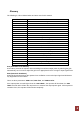
Glossary The following is a list of abbreviations and terms used in this manual. Abbreviation AC ANT ATT MHU RU EHU C.
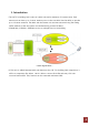
1. Introduction • The CAT-5 In-building DAS consist of a MHU unit and a maximum of 8 remote units. Each remote unit can have up to 2 server antenna ports so that one MHU has the ability to provide up to 16 server antennas. The MHU and the remote unit are interconnected using the analog CAT5e method so that the system can simultaneously provide TRI Band. (CDMA1900 / iDEN800 / iDEN900) service to multiple floors in the building.
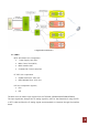
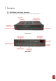
< Organization with EHU > 1-1. MHU MCU & Interface Unit components ¾ Power Supply Unit (PSU) ¾ Main Control Unit (MCU) ¾ MHU Interface Unit ¾ Command & Control Unit(C&C) RF UDC Unit components ¾ CDMA 1900 DL/UL UDC Unit ¾ iDEN 800/900 DL/UL UDC Unit PoE Unit components (Option) ¾ PSU ¾ PSE The MHU Unit can detect input signals from the TRI Band (CDMA1900/iDEN800/iDEN900).
1-2. Remote Remote Unit components ¾ Power Supply Unit (PSU) ¾ Power Supply Unit (PD)-PoE Option ¾ iDEN 800/900 UL/DL UDC Unit ¾ CDMA 1900 UL/DL UDC Unit ¾ TRI Band MUX Filter ¾ Main Control Unit (MCU) ¾ RU Interface Unit The Remote UDC Module converts the RF signal into an IF signal and compensates it for the STP or SFTP Cable loss. After the RF signal is amplified from the UDC module, it goes to all antenna ports from the remote until. 1-3.
2. Description 2.
2.1.
2.1.
2.1.3 MHU MCU(Main Control Unit) The MCU (Main Control Unit) is the control unit of the CAT5 DAS MHU. It controls and monitors operational parameters. It is also responsible for generating alarms, keeping event logs and performing many other functions.
2.1.4 MHU INTERFACE BOARD 2.1.5 MHU C&C (Command & Control Unit) C&C Board is communicating board for WEB GUI.
2.1.6 MHU PSU (Power Supply Unit) The Power Supply Unit (PSU) supplies a steady DC Power to CAT5 DAS MHU by drawing power from the general in-wall AC outlets.
2.2 Remote Overview The Remote UDC module converts the RF signal into an IF signal and compensates it for the CAT5e STP or SFTP cable loss. After the RF signal is amplified from the UDC module, it goes to all antenna ports from the remote unit.
2.2.1 Remote Internal Configuration 2.2.
2.2.3 Remote iDEN 800/900 UDC Module 2.2.
2.2.5 Remote MCU(Main Control Unit) The MCU (Main Control Unit) is the control unit of the CAT5 DAS Remote. It controls and monitors operational parameters. It is also responsible for generating alarms, keeping event logs and performing many other functions.
2.2.6 Remote Interface Board 2.2.7 Remote PSU (Power Supply Unit) The Power Supply Unit (PSU) supplies a steady DC Power to CAT5 DAS Remote by drawing power from the general in-wall AC outlets.
2.3 EHU(Extension Hub Unit) 2.3.
2.3.2 EHU Interface Board 2.3.3 EHU RFU RFU transmits IF signal to Remote after compensating the STP or SFTP Cable loss.
2.3.4 EHU MCU(Main Control Unit) The MCU (Main Control Unit) is the control unit of the CAT5 DAS EHU.
2.3.5 EHU PSU (Power Supply Unit) The Power Supply Unit (PSU) supplies a steady DC Power to CAT5 DAS EHU by drawing power from the general in-wall AC outlets.
3. Hardware Installation The installation procedure is as follows: • Check List of Items • Mounting • Grounding 3.1 Check List of Items 3.1.1 MHU of Items Index Items Quantity 1 MHU Set 1 2 UTP Cross LAN Cable 1 3 AC Cord 1 4 Anchor Bolts 8 5 RF Cable 6 6 RS-232 Cable 3 7 CD of the User’s Manual 1 8 Quick Guide 1 Item Figure 3.1.
Index Items Quantity 1 Remote Repeater 1 2 UTP Cross LAN Cable 1 3 AC Cord 1 4 Anchor Bolts 4 Item Figure 3.1.
3.2 Mounting 3.2.1 Remote Mounting CAT-5 DAS are easy to mount using the assembled mounting bracket, which has 4 holes for the provided 5/16” fixing screws. Step 1: Drill holes directly through the template. Step 2: Install the set anchor bolts or the plastic anchor bolts in the holes. Step 3: Attach the mounting bracket to the wall using provided bolts or extra screws.
Step 4: Lean the CAT-5 DAS RU to hang topside of the Guide Ring on the mounting bracket, and push toward the wall to mount. Step 5: Fix the CAT-5 DAS RU using the 6 screws provided.
3.2.2 MHU & EHU Unit Mounting MHU & EHU Unit of CAT-5 DAS is able to install at the Wall or Rack CAT-5 DAS MHU & EHU Unit의 Rack Installation CAT-5 DAS MHU & EHU unit의 Wall installation MHU and EHU Unit size is same. Repeat the step 1 to step 3 of 3.2.1 then install it as the same way. 3.
A rod on the left side is intended for a building ground. Connect the ground cable to the rod. 3.
Step 1: Connect the power cord. Step 2: Plug the power cord into a wall outlet. Step 3: Power Switch turns on. Step 4: Check if the green LED at the top turns on.
4. Operation 4.1 System Requirements CAT-5 DAS operates on a customer provided PC based platform with the following system requirements: • Windows® 2000, Windows® XP or Windows® Vista, Windows 7 • Internet Explorer 6.0(Recommended) or higher • 128 MB RAM or higher • Pentium Ⅲ processor or higher • RJ-45 jack required 4.2 Network Setup 4.2.1 Windows XP Step 1: Click the Start button and select My Network Places. Step 2: Click View network connections.
Step 3: Right-click on the Local Area Connection and select Properties to view the shortcut menu. Step 4: Select Internet Protocol (TCP/IP) and click Properties. Step 5: Check Obtain an IP address automatically and click OK. Step 6: Close all widows.
4.2.2 Windows 2000 Step 1: Click the Start button, point to Settings, and then click Network and Dial-up Connections. Step 2: Right-click Local Area Connection to see a shortcut menu and click Properties.
Step 3: Select Internet Protocol (TCP/IP) and click Properties. Step 4: Check Obtain an IP address automatically and click OK. Step 5: Close all windows.