iDEN Add-On Filter Box User’s Manual R-tron I nc.
This document describes the specifications, installation and operation of iDEN Add-On Filter Box. Hardware and software mentioned in this document are subject to continuous development and improvement. Consequently, there may be minor discrepancies between the information in the document and the performance and design of the product. Specifications, dimensions and other statements mentioned in this document are subject to change without notice. R-tron Inc.
iDEN Add-On Filter Box Contents Abbreviations .......................................................................................................................5 1. I ntroduction ...........................................................................................................6 2. Description.............................................................................................................8 2.1 System Specifications ..............................................................
iDEN Add-On Filter Box Figures Figure Figure Figure Figure Figure Figure Figure Figure Figure Figure Figure Figure Figure Figure Figure Figure Figure Figure Figure 1. 2. 3. 4. 5. 6. 7. 8. 9. 10. 11. 12. 13. 14. 15. 16. 17. 18. 19. User’s Manual R-tron iDEN Add-On Filter Box ................................................................................... 6 Overview: I nterference Filtering .................................................................................
iDEN Add-On Filter Box Abbreviations Abbreviations used in this manual, in iDEN Add-On Filter Box.
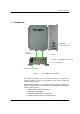
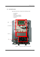
iDEN Add-On Filter Box 1. Introduction Bandwidth & Band Setup Table Filtered Output Port I nput Port Dip Switch for Bandwidth & Band Setup Screw for Grounding AC Power Socket & Switch Figure 1. R-tron iDEN Add-On Filter Box The interference within the service frequency bands is a target to be removed because it causes the degradation of the service quality and shrinking of the coverage.
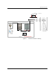
iDEN Add-On Filter Box . I nterference Donor Antenna Service Antenna Mobile Service Donor Repeater Filtered Output Base Station iDEN Add - On Filter Box Figure 2.
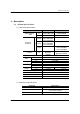
iDEN Add-On Filter Box 2. Description 2.1 System Specifications 2.1.1. Electrical Specifications Parameter Band Selection (BW) DL UL 18MHz Frequency Selection DL 7MHz 5MHz Roll off DL Gain ripple DL Gain UL DL Delay UL DL VSWR UL Input DL Range UL Power supply Operating temperature Storage temperature Consumption power iDEN 800 In-band BW:18M In-band BW:7.0M In-band 18M 851~869MHz 850.8~868.8MHz 850.8~868.6MHz 862~869MHz 861.8~868.8MHz 861.6~868.
MAKER : R-tron lnc. E258109 I.T.E 31CY MODEL NO. : RSP-AIT-R001 ELECTRICAL RATING : 100-240V ~ , 50/60Hz, 1A COMPLIES WITH PART 24, FCC RULES. FCC REG. NO. : STESPAITR001 SERIAL NO. / DATE : MADE IN KOREA iDEN Add-On Filter Box 8 00 M BS 1 8 M Hz 7 M Hz 1 8B FS 1 8 5 1 ~8 6 9 M Hz 8 5 1 ~8 6 9 M Hz 8 5 0 .8 ~8 6 8 .8 M Hz 8 5 0 .6 ~8 6 8 .6 M Hz 7 B FS 2 8 6 2 ~8 6 9 M Hz 8 6 2 ~8 6 9 M Hz 8 6 1 .8 ~8 6 8 .8 M Hz 8 6 1 .6 ~8 6 8 .6 M Hz 9 00M FS 3 9 3 5 ~9 4 0 MH z 9 3 5 ~9 4 0 MH z 9 3 4 .
iDEN Add-On Filter Box 2.2 Sub Unit Overview iDEN Add-On Filter Box is composed of the following sub units: Filter Module Duplexer Main Control Unit (MCU) Power Supply Unit (PSU) EMI Filter MCU Filter Module Duplexer PSU Figure 4.
iDEN Add-On Filter Box 2.2.1. Block Diagram The following, Figure 5, explains how the unit filters signals. FB iDEN SAW Filter with Programmable options 851~869 / 850.8~868.8 / 850.6~868.6 MHz with -65dBc@±500KHz 18MHz Donor antenna Service antenna 7MHz Filter 851~869MHz Filter 806~824MHz iDEN Repeater Filter SAW Filter with Programmable options 851~869 / 850.8~868.8 / 850.6~868.
iDEN Add-On Filter Box 2.2.2. Filter Module The Filter Module is basically a complex band-pass filter that sharply filters out unwanted noise. Output Port I nput Port Figure 6.
iDEN Add-On Filter Box 2.2.3. Duplexer A duplexer is a device that combines two or more signals onto a common channel or medium to increase its transmission efficiency. 800/ 900MHz I nput 900MHz Input Input CPL -10dB 800MHz I nput Figure 7.
iDEN Add-On Filter Box 2.2.4. MCU (Main Control Unit) MCU is the control unit of iDEN Add-On Filter Box. It controls and monitors operational parameters. It also generates alarms, an event log and many other functions of the iDEN Add-On Filter Box. USB1A_J1 MOL4 LED1 MOL1 LED2 LED3 MOL3 Figure 8.
iDEN Add-On Filter Box 2.2.5. Power Supply The Power Supply Unit (PSU) supplies a steady DC power to iDEN Add-On Filter Box by drawing power from the general in-wall AC outlets Figure 9. Power Supply Specifications Item Operating Temp Environmental Storage Temp -20℃~70℃ Humidity 20%~90%RH Cooling method Natural air Voltage User’s Manual Specifications -10℃~60℃ AC85~264V Current 4.2A Max / 12Vdc Frequency Leakage Current 47~440Hz max (50~60Hz typ) 0.5mA max.