
User's Manual

RV-QUADCOMM USER’S MANUAL V1.0.00 Tech Support: 1-888-317-8766
36
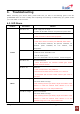
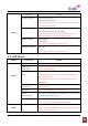
Check Point Solution
DPL LED is orange Donor power too low
- DL Donor Power too low
- If the DL input Power is too low, adjust the location and/or
azimuth of the antenna.
CCF LED is orange Coverage Circuit failure
- UL Power at coverage high, DL VSWR
- If the DPL LED is normal but the CCF LED is in alarm,
check mobile device for excessive TX power level.
RE LED is orange Reset engaged
- Reset alarm
- Do not control the Repeater during reset.
Problem
AGC LED is orange AGC active
- AGC On
- It means that AGC is On and operating.
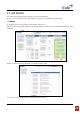
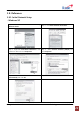
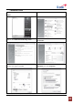
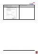
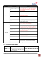
6.2. GUI Alarm
Problem Check Point Solution
Tamper detected Install the RF Card and set the Lock using the WEB GUI.
Power supply
out of range
- Check if the input power is AC85-264V and if it is normal,
Contact Technical Support.
Communication
failure
Check the status of the Data Cable connection.
If communication failure occurred at every connected RF
Card, Reset the MCU.
If communication failure occurred at a particular RF Card,
Reset RF Card.
Field replaceable
module failure
If the same alarm occurs after resetting the RF Card, request
technical support.
General
Reset alarm Do not control anything during the reset.
Manual
shutdown alarm
This may be caused when any of DL and UL path controls
are off by Manual gain setting.
Heartbeat Check the connection of the Remote NMS Cable.
Check the interval of Heartbeat on the WEB GUI.
Uplink
Oscillation detected Check Donor/Server antenna Isolation value. If the gain
value is lower than repeater gain +15dB, adjust the antenna
location and or reduce gain.