
User Manual
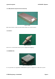
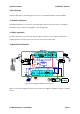
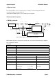
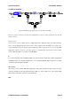
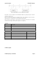
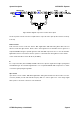
Table Of Contents

System Description NOTCHCELL Repeater
8: Transmit Power Monitor
9: Reflect Power Monitor
Mute Function 5V( Off, 0V(On
Power Detector 0.1 ~ 5V
Voltage DC 27V
RF connector Type-SMA, female
( ( ( ( ( ( (
5.2 PA for uplink
3
EMBED V
4! 5
isio.Drawing.6 Figure 17 Block diagram of Power Amplifier unit for uplink
PA (Power Amplifier) amplifies RF signal received from UDC (Downlink) up to 40dB and its Maximum RFOutput
is 30dBm in terms of CDMA SFA standards.
Connection
Port Connected to
RF IN RF OUT on the UDC-UL board.
RF OUT UL on the DPX-BS duplex filter.
CON On the ARCU board.
CON +27V on the PSU unit.
Specification
Item Specification Remarks
Frequency 1870MHz ~1885MHz
Bandwidth 15MHz
Gain
40
±
0.5dB
Output Power 30 dBm
I/O Port
1: GND 2: Over Power Alarm
3: VSWR Alarm 5: Over Temp
6: PA On/Off 7: Cable Open
8: Transmit Power Monitor
9: Reflect Power Monitor
Normal: Low
Fail: High
Mute Function
5V
⇒
Off, 0V(On
Power Detector 0.1 ~ 5V
Voltage DC 27V
RF connector Type-SMA, female
R-TRON Proprietary & Confidential Page 17