
User Manual

System Description NOTCHCELL Repeater
R-TRON Proprietary & Confidential Page 18
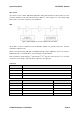
I/O Port
1: GND 2: Over Power Alarm
3: VSWR Alarm 5: Over Temp
6: PA On/Off 7: Cable Open
8: Transmit Power Monitor
9: Reflect Power Monitor
Normal: Low
Fail: High
Mute Function
5V
⇒
Off, 0V
⇒
On
Power Detector 0.1 ~ 5V
Voltage DC 27V
RF connector Type-SMA, female
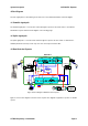
5.3 UDC for downlink
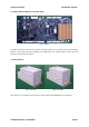
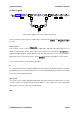
Figure 18 Block diagram of Up-Down converter unit for downlink
The above product is Un-Down Converter for Downlink and it is composed of three parts (Down Converter, IF
and Up Converter)
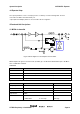
Down Converter
Down Converter consists of RF level detector, BPF, Digital Atten, AMP and Analog Atten, Mixer. RF level
detector converts RF signal into DC, which is able to detect signal level. The first BPF removes signal out of
required bandwidth among the inputted signal from LNA and AMP compensates the loss from the first BPF.
Digital Atten, which is connected to Controller, operates to control Path Gain. Analog Atten is used for minute
control of Path Gain. Mixer converts RF into IF (IF-70MHz)
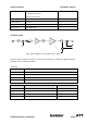
IF
IF is composed of Filter (LPF and SAW) and AMP. LPF removes spurious signal which is higher passing band
and SAW Filter gets rid of unwanted signal which is out of required bandwidth. AMP compensates loss which
occurs when signal passing through Filter.