
User's Manual

#2':75'4/#07#.86GEJ5WRRQTV
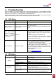
Troubleshooting
Before contacting your service dealer, refer to the following guidelines. If the APEX8930 repeater
does not work normally after completing the following troubleshooting, please contact your local
dealer or R-tron America’s Tech support line (1-888-31R-TRON).
External alarm lamps on the front of the repeater indicate current condition. Green lamp indicates
power to the repeater, yellow indicates caution, and red indicates shut sown
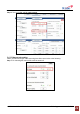
LED Alarm
Problem Cause Solution
No LED on Power failure Check the power cord for secure connection
Mobile device has
poor performance.
Repeater service degraded
or not available.
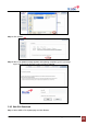
Login to the web GUI.
Check the setting, alarm status and input/output power
status.
Gain, Input/ Output
power or DC Current
are changing
randomly or appear
to be unstable.
Oscillation
Most common cause for unstable gain and power is
feedback oscillation brought on by insufficient antenna
isolation.
1. Reduce repeater gain and/or AGC level.
2. Improve the field conditions that cause poor antenna
isolation: For example: make an effort to increase
downlink input and reduce gain.
The red light is on. Automatic Shutdown
Automatic shutdown occurs when the amplifier is over
driven. The amplifier is most commonly overdriven by:
1. Oscillation due to poor antenna isolation.
2. High input power combined with high gain settings
including high UL input from the mobile device.
User the alarm history page to help determine the
cause of the shutdown. Eliminate the root cause of the
shutdown and restart the repeater.
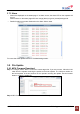
Technical Support
Web site: www.r-tronamerica.com
Toll Free: 888-317-8766
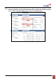
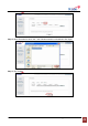
GUI Alarm
Problem Check Point Solution
DC Current
If the same alarm occurs after reset Power, request
technical support.
Temperature
Execute of System Reset (NCU) on Network Setup
page. If the same alarm occurs request technical
support.
Automatic Shutdown Check Isolation and DL/UL Input power..
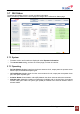
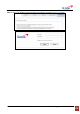
General
Heartbeat
Check the connection of the Remote NMS Cable.
Check the interval of Heartbeat on the WEB GUI
DL Input Power
DL Input alarm can be the result of low signal level from
the donor antenna circuit.
Tune the antenna and/or reduce feeder line loss.
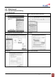
Downlink
DL Output Power
Check DL input Power.
If input power exceeds max input power install an
attenuator on the donor antenna transmission line.