APEX8930 SMR Band Repeater User’s Manual Please read this manual before operating this product. After you finish reading this manual, store it in a safe place for future reference.
TABLE OF CONTENTS 1.G GENERAL G 1.1G NOTICE G 1.
5.4.4G User Comment G 5.5G GUI SYSTEM CONTROL G 5.5.
General Notice Trademark R-tron is a registered trademark of R-tron Inc. Other products and company names mentioned here in this manual might be trademarks or trade names of their respective owners. Copyright Copyright © R-tron Inc. 2000-2011 All Rights Reserved Any reproduction, distribution, or revisions of any or all portions of this manual is prohibited without written permission from R-tron Inc.
Safety Precautions Opening the APEX8930 equipment could result in electric shock and may cause severe injury. Connect the equipment frame ground to the building ground. Operating the APEX8930 with antennas in very close proximity facing each other can lead to severe damage to the repeater. RF EXPOSURE INFORMATION A minimum separation distance of 7.9 inches (20cm) must be maintained between the user and the external antenna of the repeater to satisfy FCC RF exposure requirements.
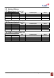
Version History Manual Version History List Revision History Approval Ver. Issue Ver. V1.0 V1.0 Date Item/Description Reason Item/Description Reason Item/Description Reason Firmware Version History List Revision History Approval Ver. Issue Ver. Date WEB GUI Version History List Revision History Approval Ver. Issue Ver. Date #2': 75'4 /#07#.
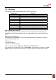
Glossary The following is a list of abbreviations and terms used in this manual. Abbreviation AC DC DL GUI LED MCU NCU PSU RF UL VSWR Definition Alternating Current Direct Current Downlink Graphic User Interface Light Emitting Diode Main Control Unit Network Control Unit Power Supply Unit Radio Frequency Uplink Voltage Standing Wave Ratio AGC (Automatic Gain Control) AGC prevents the repeater from exceeding its maximum output power by reducing the gain automatically.
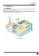
Introduction APEX8930 APEX8930 is used to fill out areas that may have poor cellular coverage, such as base station fringe areas, business and industrial building, etc. APEX8930 receives signals from a base station, amplifies and retransmits the signals to the mobile stations. It also receives, amplifies and retransmits signals in the opposite direction. Both directions are served simultaneously with the following features: #2': ': #2 < Basic Organization > #2': 75'4 /#07#.
APEX8930 Key Features ඞ Design - Multiple APEX repeaters may be stacked together to created quad band service with a single control interface. - Digital filtering allows for customized channel selections. - Digital filtering features high quality, out of band rejection, and high performance ඞ User friendly design. - Local monitoring and control through the Web GUI interface - Remote monitoring and control through the Web GUI interface.
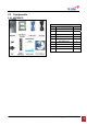
Components APEX8930 APEX8930 Package Index Items Q’ty 1 Repeater 1 2 Wall Mount Bracket 1 3 LAN Cable 1 4 5 AC Cable Bolt (M4*8mm) 1 2 6 Bolt (M6*12mm) 4 7 Direct LAN Cable 1 8 Quick Guide 1 9 User’s Manual CD 1 #2': 75'4 /#07#.
Description Overview #2': 75'4 /#07#.
Internal Configuration RFU (RF Unit) The RFU (RF Unit) is a bi-directional amplifier that sharply filters out unwanted noise. Multiplexer A Multiplexer is a device that combines two or more signals onto a common channel or medium to increase its transmission efficiency. PSU (Power Supply Unit) The AC-DC adaptor supplies a steady DC power to the APEX8930 equipment by drawing power from the general in-wall AC outlets.
Mechanical Installation The installation procedure is as follows: • Confirm Items from List • Mounting • Grounding • RF Cable Connection • Power On Mounting Step 1 Drill holes directly through the template. Attach the mounting bracket to the wall using provided bolts (16/5*50mm) or extra screws. Step 2 Lean the APEX8930 to hang the topside of the Guide Ring on the mounting bracket, and push toward the wall to mount. Step 3 Fix the repeater using the 4 bolts (M6*12mm) provided.
Step 4 Fix the repeater using the 2 bolts (M4*8mm) provided. Step 5 Connecting multiple APEX repeaters. #2': 75'4 /#07#.
Cable Installation Cable Connection Step 1: Connect a cable from the donor antenna to the Donor Antenna Port. Step 2: Connect a cable from a repeater’s service antenna to the Sever Antenna Port. Power On Notice: Antenna cables must be installed before connecting AC Power. #2': 75'4 /#07#.
Step 1: Connect the power cord to the Repeater Step 2: Plug the power cord into a wall outlet. Step 3: Turn the red power button on Step 4: Check if the green LED at the Top turns on. Grounding Step 1: A rod on the left side is intended for a building ground. Step 2: Connect the ground cable to the rod. #2': 75'4 /#07#.
GUI Operation APEX8930 operates on a customer provided PC based platform with the following system requirements: • Windows® XP or Windows® Vista, Windows 7 • Internet Explorer 6.0(Recommended) or higher • 128 MB RAM or higher • Pentium ๊ processor or higher • RJ-45 Cable required GUI Operation Flow Chart #2': 75'4 /#07#.
Internet Network Setup Windows 7 (Refer to 5.9 for other versions of Windows) Step 1: Click the Start button and select Control Panel. Step 2: Click Network and Internet. Step 3: Click Network and Sharing Center. Step 4: Click View status of Local Area Connection. Step 5: Click Properties and a caution pop-up window will appear. Click OK. Step 6: Select Internet Protocol Version 4 (TCP/IPv4) and click Properties. Step 7: Check Obtain an IP address automatically and click OK.
System Login For APEX8930 operation access, go to Web GUI and Log in. Step 1. Open your Web browser and type http://192.168.0.1 into the URL address box. Then press the Enter key. Step 2. Confirm a User ID and type the password into the password box. The user name is “operator”, the password shoule be “rtron” to be consistent with our legacy repeaters. Click OK. Step 3. The pop-up message for the login success message will appear. Click OK. Step 4.
System Setup Time Setting The time will automatically set to your PC time when you click the set time In the above page, you can set system time and update time-related information. Network Setup #2': 75'4 /#07#.
¾ SYSTEM • Cascade Code: Type the pre-assigned cascade code (site I.D); otherwise, you cannot access the system setup. Set up for multiple bands. One repeater with installed NCU is designated as the master control. The other repeaters will connect to the master via RJ45 cable. The master web GUI will display the other repeaters if the connection is successful. ȄG Cascade code 1 box of SYSTEM in Network setup. ȄG When adding repeaters refer to the RJ45 cable connection below.
¾ • Location Information: Enter the latitude and longitude. You can input values either in Decimal Degrees or Degrees-Minutes-Seconds. [Example] (‘N/S’ | ‘E/W’) ddd.dddddd: (Latitude: N 39.006967 Longitude: W 94.532306) • Refresh Time: Set each refresh time for connecting to Local port and Remote port. ETHERNET SETTING • Ethernet IP Mode/IP Address: Enables you to set a connection mode for the network connected to the APEX8930 remote LAN port.
G User Comment G User Comment: The user can store up to 50 comments in memory. The length of each comment is limited to 20 characters. G GUI System Control #2': 75'4 /#07#.
System Control G Easy Setup is a fast start function. The function measures isolation, detects input level and assing gain to achieve maximum output power. The function ends with the repeater set to amplify siganals in both directions within the confines of the band selection. Before running easy setup, set the center frequency and bandwidth (refer 5.5.4). G Isolatoin Check can be executed at anytime to measure isolation between the donor and server antennas.
G DL and UL Path Control allows the user to toggle on or off the power amplifiers. G DL and UL Gain is available when AGC mode is off. The user may enter gain values manually. Manual gain control is an alternative to autonatic gain control(AGC). Manual gain is disabled (grayed out) when AGC mode is on. Gain cannot be controlled manually above the available gain found on the status page. The system will not allow gain to be increased such that maximum output power(30dBm) is exceeded.
Band Select G Band select sets the digital filter to the center frequency and bandwidth of the local service for which the repeater is intended to amplify. Likewise, all other signals outside of the selected Center Frequency and Bandwidth are not amplified. G The user can select one or two or three distinct section within the iDEN band. Each of the 1st, 2nd and 3rd filter blocks can be set to 1MHz to 18MHz of Bandwidth(800MHz). For 900MHz Bandwidth is 1MHz to 5MHz.
Step 2. Input AGC Level desired and click Apply. 1) AGC Level 30dBm 2) AGC Level 20dBm Step 3. Easy Setup proceeds to: G Data Initial execution G Isolation Test exeduted G Calculation of Available Maximum Gain by the isolation G DL/UL Path On G AGC On to obtain DL Output Power AGC Level or Maximum Gain 85dB G ASD On G AGC Off G Easy setup takes about 2minutes. Click Execute button of Easy Setup Step 4. Click OK. 1) AGC Level 30dBm #2': 75'4 /#07#.
2) AGC Level 20dBm Step 5. Setup will automatically begin. This process takes approximately 3 minutes. Result 1. Constant Maximum DL Output Power 30dBm (AGC Level 30dBm) If the DL input Power -55dBm #2': 75'4 /#07#.
Result 2. Constant Maximum DL Output Power 27dBm (AGC Level 20dBm) If the DL input Power -55dBm Manual Gain Setting AGC mode On Setting Step 1. Repeat Step 1 through Step 2 Step 2. Isolation Check The Isolation will calculate the Available Maximum Gain which defines the maximum gain to be setup. Click Isolation #2': 75'4 /#07#.
Step 3. Click OK. Step 4. When below pop-up appears after Isolation is completed, click OK. Step 5. AGC must be turned on. AGC automatically assigns gain in accordance with AGC level. Use AGC level to increase or decrease gain. (Gain Offset is a gain differential between DL Output gain and UL output gain.) Ex>AGC Level 30dBm, Gain Offset -3dB ĺ DL Gain 85dB, UL Gain 82dB AGC Level 30dBm, Gain Offset 0dB ĺ DL Gain 85dB, UL Gain 85dB #2': 75'4 /#07#.
Step 6. Turn on the DL and UL path controls. Manual gain setting When you want to set gain value not using Auto Gain control refer to the following. Step 1. For manual gain control AGC must be turned off. #2': 75'4 /#07#.
Step 2. The user can select any gain value as long as it does over-drive the amplifier or exceed isolation requirements. Gain is automatically limited where conditions do not permit high gain. Select the DL and UL Gain values. Turn on the DL and UL path controls. #2': 75'4 /#07#.
GUI Status The status page display system, control, and alarm information. When you set any value on the Control page the change will be reflected on Status page. System G Firmware version and location are displayed under Repeater Information. G The current band setting, set from the control page, is shown in bold font. Operating G DL Path Monitor displays input from the donor antenna circuit, output power at repeater server antenna port, and downlink amplifier gain.
Alarm G Alarms are displayed on the status page. If an alarm occurs, the alarm LED on the repeater will turn on. Alarms shown on the status page will have orange (alarm) or green (normal) background. G Details for alarm events are displayed on the Alarm History page. For corrective action please refer to 6. Troubleshooting section. File Update MCU Firmware Download Step 1. For target, sellect “MCU“. Choose the correct target slot.
Step 3. Click Update. Step 4. When File update message appears and updating completed, go to Log-in page. Log-in and confirm the firmware version has been updated. Web GUI Download Step 1. Select WEB in File Update page and click Browse. #2': 75'4 /#07#.
Step 2. Select Firmware file which has “.web“ filename extention to download. Click Open. Step 3. Click Update. #2': 75'4 /#07#.
Step 4. When File update message appears and updating completed, go to Log-in page. #2': 75'4 /#07#.
Attachment 5.9.1 Internet Network Setting Window XP Step 1: Click the Start button and select My Network places. Step 2: Click View network connections. Step 3: Right-click on the Local Area Connection and select Properties to view the shortcut menu. Step 4: Select Internet Protocol (TCP/IP) and click Properties. Step 5: Check Obtain an IP address automatically and click OK. Step 6: Close all widows. #2': 75'4 /#07#.
Windows Vista Step 1: Click the Start button and select Control panel. Step 2: Click Network and Internet Step 3: Click Network and Sharing Center. Step 4: Click View status of Local Area Connection. Step 5: Click Properties and a caution pop-up window will appear. Click OK. Step 6: Select Internet Protocol Version 4 (TCP/IPv4) and click Properties. Step 7: Check Obtain an IP address automatically and Click OK. Step 8: Close all windows. #2': 75'4 /#07#.
Troubleshooting Before contacting your service dealer, refer to the following guidelines. If the APEX8930 repeater does not work normally after completing the following troubleshooting, please contact your local dealer or R-tron America’s Tech support line (1-888-31R-TRON). External alarm lamps on the front of the repeater indicate current condition.
VSWR Uplink UL Output Power VSWR alarm is the result of o poorly matched antenna circuit. The repeater is almost never the reason for return loss issues. A good quality 50 ohm load placed over the repeater server port or donor port will extinguish the alarm and prove the alarm is caused by some external antenna issue. UL output power alarm is red when the UL output exceeds rated amplifier output.
Communication log-in problem When you can’t log in to the web GUI. Solution 1. Click My Network places Æ View network connections. Right-click on the Wireless Network Connection and then click Disable. 2. Right-click on the Local Area Connection and then click Disable. After clicking Disable, click Enable again. 3. Double click the Local Area Connection and then click the Support tab Æ Repair. #2': 75'4 /#07#.
Solution 4. Open the Internet Browser, select Tools Æ Internet Options. Click Delete Files in the Temporary Internet files section. 5. Click Start and select Run. Type “ping 192.168.0.1-t” and click OK. #2': 75'4 /#07#.
Specifications RF Characteristics Electrical Specifications iDEN 800M+900M Band Parameter Frequency Range Remark TX(Down-Link) TX(Down-Link) RX(Up-Link) RX(Up-Link) 851 - 869 MHz (18M B.W) 935 ~ 940MHz (5M B.W) 806 - 824 MHz (18M B.W) 896 ~ 901MHz (5M B.
Environmental Specification Parameter Specification Operating Temp -10˚C~50˚C (14˚F~122˚F) Humidity 20%~90%RH Cooling method Convection. Environmental Electrical Specification Parameter Specification Voltage Current Frequency AC 85-264V +24V/7.5A (150W) 50/60(47-63) Mechanical Specification Parameter Specifications RF connectors N-female x 2 Dimensions (WxHxD) 12.09 * 21.69 * 6.24 inch 307 * 551 * 158.5 mm Weight 50.71 lb 23 Kg max Remark W*D*H #2': 75'4 /#07#.
Appendix iDEN Channel Frequency Information ( iDEN ) Select Band & BW Band Down(Donor) Link Up(Server) Link Offset (kHz) B.W (MHz) Center (MHz) Start (MHz) Stop (MHz) Center (MHz) Start (MHz) Stop (MHz) 18 860 851 869 815 806 824 0 17.8 860 851 868.8 815 806 823.8 200 17.6 860 851 868.6 815 806 823.6 400 7 865.5 862 869 820.5 817 824 0 6.8 865.5 862 868.8 820.5 817 823.8 200 6.6 865.5 862 868.6 820.5 817 823.6 400 5 937.5 935 940 898.
Warranty LIMITED WARRANTY This product, as supplied and distributed by R-tron, in the original carton, is warranted by R-tron against manufacturing defects in materials and workmanship for a limited warranty period of: Five (5) Year Parts and Labor This limited warranty begins on the original date of purchase, and is valid only on products purchased and used in the United States.
Return Material Authorization (RMA) Procedure The return and exchange of products are not allowed without prior approval from R-tron America, Inc. Please follow the exchange procedure below. 1. Call Tech Support for troubleshooting. 2. If the device has a hardware problem, R-tron will replace it if it is within warranty. A RMA number will be issued for the return. 3. R-tron will ship the replacement unit with a return shipping label. 4.