APEX730 LTE Band Repeater User’s Manual Please read this manual before operating this product. After you finish reading this manual, store it in a safe place for future reference.
TABLE OF CONTENTS 1. GENERAL........................................................................................................................................................... 1 1.1 NOTICE .............................................................................................................................................................................................1 1.2 SAFETY PRECAUTIONS ....................................................................................................
4.5.2 Operating Control................................................................................................................................................................ 20 4.5.3 Alarm Control ....................................................................................................................................................................... 21 4.5.4 Band Select ....................................................................................................................
1. General 1.1 Notice Trademark R-tron is a registered trademark of R-tron Inc. Other products and company names mentioned here in this manual might be trademarks or trade names of their respective owners. Copyright Copyright © R-tron Inc. 2000-2011 All Rights Reserved Any reproduction, distribution, or revisions of any or all portions of this manual is prohibited without written permission from R-tron Inc.
1.2 Safety Precautions Opening the APEX730 equipment could result in electric shock and may cause severe injury. Connect the equipment frame ground to the building ground. Operating the APEX730 with antennas in very close proximity facing each other can lead to severe damage to the repeater. RF EXPOSURE INFORMATION A minimum separation distance of 7.9 inches (20cm) must be maintained between the user and the external antenna of the repeater to satisfy FCC RF exposure requirements.
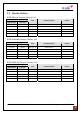
1.3 Version History 1.3.1 Manual Version History List Revision History Approval Ver. Issue Ver. V1.0 V1.0 Date Item/Description 2011. 06. 15 Initial Version Reason 1.3.2 Firmware Version History List Revision History Approval Ver. Issue Ver. V1.0.00 V1.0.00 Date Item/Description 2011. 06. 15. Initial Version Reason 1.3.3 WEB GUI Version History List Revision History Approval Ver. Issue Ver. V1.0.00 V1.0.00 Date Item/Description 2011. 06. 15 Initial Version APEX730 USER MANUAL V1.0.
1.4 Glossary The following is a list of abbreviations and terms used in this manual. Abbreviation AC Definition Alternating Current LTE Long Term Evolution Direct Current Downlink Graphic User Interface Light Emitting Diode Power Supply Unit Radio Frequency Uplink Voltage Standing Wave Ratio Network Control Unit Main Control Unit DC DL GUI LED PSU RF UL VSWR NCU MCU AGC (Automatic Gain Control) AGC prevents the repeater from exceeding its maximum output power by reducing the gain automatically.
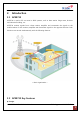
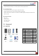
2. Introduction 2.1 APEX730 APEX730 is used to fill out areas in APEX systems, such as base station fringe areas, business and industrial building, etc. APEX730 receives signals from a base station, amplifies and retransmits the signals to the mobile stations. It also receives, amplifies and retransmits signals in the opposite direction. Both directions are served simultaneously with the following features: < Basic Organization > 2.2 APEX730 Key Features ◈ Design APEX730 USER MANUAL V1.0.
- Digital filtering allows for customized channel selections. - Digital filtering high quality, out of band rejection, and high performance ◈ User friendly design. - Local monitoring and control through the Web GUI interface - Remote monitoring and control through the Web GUI interface. - Reports the status of connection as a function of SNMP regularly and reports an alarm if the event occurred. ◈ Protection function - Easy setup - Isolation Check - Auto Gain Control - Auto Shutdown 2.3 Component 2.3.
2.4 Description 2.4.1 Overview APEX730 USER MANUAL V1.0.
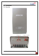
2.4.2 Internal Configuration 2.4.3 RFU (RF Unit) The RFU (RF Unit) is a bi-directional amplifier that sharply filters out unwanted noise. 2.4.4 Duplexer A duplexer is a device that combines two or more signals onto a common channel or medium to increase its transmission efficiency. 2.4.5 PSU (Power Supply Unit) The AC-DC adaptor supplies a steady DC power to the APEX730 equipment by drawing power from the general in-wall AC outlets. 2.4.
3. Mechanical Installation The installation procedure is as follows: • Confirm Items from List • Mounting • Grounding • RF Cable Connection • Power On 3.1 Confirm Item from List APEX730 Package 3.2 Index Items Q’ty 1 Repeater 1 2 Wall Mount Bracket 1 3 LAN Cable 1 4 AC Cable 1 5 Bolt (M4*8mm) 2 6 Bolt (M6*12mm) 4 7 Bolt (16/5*50mm) 4 8 Direct LAN Cable 1 9 Quick Guide 1 10 User’s Manual CD 1 Mounting Step 1 Drill holes directly through the template.
Step 2 Lean the APEX730 to hang the topside of the Guide Ring on the mounting bracket, and push toward the wall to mount. Step 3 Fix the repeater using the 4 bolts (M6*12mm) provided. APEX730 USER MANUAL V1.0.
Step 4 Fix the repeater using the 2 Bolts (M4*8mm) provided. APEX730 USER MANUAL V1.0.
3.3 Grounding Step 1: A rod on the left side is intended for a building ground. Step 2: Connect the ground cable to the rod. 3.4 RF Cable Connection Step 1: Connect a cable from the donor antenna to the Donor Antenna Port. Step 2: Connect a cable from a repeater’s service antenna to the Sever Antenna Port. APEX730 USER MANUAL V1.0.
3.5 Power On Notice: Antenna cables must be installed before connecting AC Power. Step 1: Connect the power cord to the Repeater Step 2: Plug the power cord into a wall outlet. Step 3: Turn the red power button on Step 4: Check if the green LED at the Top turns on. 4. GUI Operation APEX730 operates on a customer provided PC based platform with the following system requirements: • Windows® XP or Windows® Vista, Windows 7 • Internet Explorer 6.
• RJ-45 Cable required 4.1 GUI Operation Flow Chart [1] Internet Network Setup [2] GUI Log-in Setting in order to acquire the IP APEX730 operation access to address automatically. Web GUI and Log in. [3] GUI Network Setup 1. Time Setting Automatically set to your PC time. 2. System Information Input Input Cascade Code 3. Ethernet Setting IP address and SNMP IP Input. and Location Information. [4] GUI System Control The user can control the repeater locally using the built-in WEB GUI. 1.
4.2 Internet Network Setup 4.2.1 Windows 7 (Refer to 5.9 for other versions of Windows) Step 1: Click the Start button and select Control Panel. Step 2: Click Network and Internet. Step 3: Click Network and Sharing Center. Step 4: Click View status of Local Area Connection. Step 5: Click Properties and a caution pop-up Step 6: Select Internet Protocol Version 4 (TCP/IPv4) window will appear. Click OK. and click Properties. APEX730 USER MANUAL V1.0.
Step 7: Check Obtain an IP address automatically and click OK. Step 8: Close all windows. 4.3 System Login For APEX730 operation access, go to Web GUI and Log in. Step 1. Open your Web browser and type http://192.168.0.1 into the URL address box. Then press the Enter key. Step 2. Confirm a User ID and type the password into the password box. User ID is “operator”, Type “rtron” for the password and then click OK. Step 3. The pop-up message for the login success will appear. Click OK. Step 4.
4.4 System Setup When you click Network you can set up User Note, Comment, Ethernet, and time setting. 4.4.1 Time Setting The time will automatically set to your PC time when you click the set time In the above page, you can set system time and update time-related information. 4.4.2 Network Setup ¾ SYSTEM • Cascade Code: Type the pre-assigned cascade code. Otherwise, you cannot access the system setup. ¾ ETHERNET SETTING APEX730 USER MANUAL V1.0.
• Ethernet IP Mode / IP Address: Enables you to set a connection mode for the network connected to the APEX730 remote LAN port. When you “select” Auto, the device automatically assigns the IP address. When you select “Static”, it is possible to set an IP address of your choosing. • SNMP: In order to send Heartbeat and alarm related information to a remote monitoring server, you can set a server IP address. The factory default IP address is 10.22.25.15.
4.5.1 System Control • Easy Setup is a fast start function. The function measures isolation, detects input level and assign gain to achieve maximum output power. The function ends with the repeater set to amplify siganals in both directions within the confines of the band selection. Before runing easy setup, set the center frequency and bandwidth Maximum output power requires at least -60dBm input power and suficient antenna isolaiton.
4.5.2 Operating Control • DL and UL Path Control allows the user to toggle on or off the power amplifiers. • DL and UL Gain is available when AGC mode is off. The user may enter gain values manually. Manual gain control is an alternative to automatic gain control(AGC). Manual gain is disabled (grayed out) when AGC mode is on. Gain cannot be controlled manually above the available gain found on the status page.
evenually shutdown the amplifier permanently and trigger the external shutdown lamp. - ASD Level is set to 33dBm by default. It is not necessary to change the default level. 4.5.3 Alarm Control • Alarm response time may be set between 1 and 5 minutes. • Alam Mask allows the user to customize the type of alarms sent to the SNMP server when remote monitoring is in use. 4.5.
4.6 GUI System Setup 4.6.1 Easy Setup Step 1. Click Apply after setting Center Frequency and Band Width in use. Step 2. Input AGC Level desired and click Apply. 1) AGC Level 30dBm 2) AGC Level 25dBm Step 3. Easy Setup proceeds to: • Data Initial execution • Isolation Test exeduted • Calculation of Available Maximum Gain by the isolation • DL/UL Path On • AGC On to obtain DL Output Power AGC Level or Maximum Gain 90dB • ASD On • AGC Off • Easy setup takes about 60seconds.
Click Execute button of Easy Setup Result 1. Constant Maximum DL Output Power 30dBm (AGC Level 30dBm) If the DL input Power ≥ -60dBm Result 2. Constant Maximum DL Output Power 20dBm (AGC Level 20dBm) If the DL input Power ≥ -71dBm APEX730 USER MANUAL V1.0.
4.6.2 Manual Gain Setting 4.6.2.1 AGC mode On Setting Step 1. Repeat Step 1 through Step 2 Step 2. Isolation Check The Isolation will calculate the Available Maximum Gain which defines the maximum gain to be setup. Click Isolation Step 3. AGC must be turned on. AGC automatically assigns gain in accordance with AGC level. Use AGC level to increase or decrease gain. (Gain Offset is a gain differential between DL Output gain and UL output gain.
Step 4. Turn on the DL and UL path controls. 4.6.2.2 AGC mode Off setting When you want to set gain value not using Auto Gain control refer to the following. Step 1. For manual gain control AGC must be turned off. APEX730 USER MANUAL V1.0.
Step 2. The user can select any gain value as long as it does over-drive the amplifier or exceed isolation requirements. Gain is automatically limited where conditions do not permit high gain. Select the DL and UL Gain values. Turn on the DL and UL path controls. APEX730 USER MANUAL V1.0.
4.7 GUI Status The status page display system, control, and alarm information. When you set any value on the Control page the change will be reflected on Status page. 4.7.1 System • Firmware version and location are displayed under Repeater Information. • The Band Information setting, set from the control page, is shown in bold font. 4.7.2 Operating • DL Path Monitor displays input from the donor antenna circuit, output power at repeater server antenna port, and downlink amplifier gain.
Alarms shown on the status page will have orange (alarm) or green (normal) background. • Details for alarm events are displayed on the Alarm History page. For corrective action please refer to 6. Troubleshooting section. 4.8 File Update 4.8.1 MCU Firmware, Web GUI Download Step 1. If you are not sure, follow the LAN cable from the repeater receiving the update to the host repeater. The LAN port number on the host repeater is the slot number for the repeater receiving the update.
Step 2. NCU firmware file has a “.RTR“ filename extention. Click Open. Step 3. Click Update. Step 4. When File updating completed, go to Log-in page. Log-in and confirm the firmware version has been updated. APEX730 USER MANUAL V1.0.
4.9 Attachment 5.9.1 Internet Network Setting 4.9.1.1 Window XP Step 1: Click the Start button and select My Network places. Step 2: Click View network connections. Step 3: Right-click on the Local Area Connection Step 4: Select Internet Protocol (TCP/IP) and click and select Properties to view the shortcut menu. Properties. Step 5: Check Obtain an IP address automatically and click OK. APEX730 USER MANUAL V1.0.00 Step 6: Close all widows.
4.9.1.2 Windows Vista Step 1: Click the Start button and select Control panel. Step 2: Click Network and Internet Step 3: Click Network and Sharing Center. Step 4: Click View status of Local Area Connection. Step 5: Click Properties and a caution pop-up Step 6: Select Internet Protocol Version 4 (TCP/IPv4) window will appear. Click OK. and click Properties. Step 7: Check Obtain an IP address automatically and Click OK. APEX730 USER MANUAL V1.0.00 Step 8: Close all windows.
5. Troubleshooting Before contacting your service dealer, refer to the following guidelines. If the APEX730 repeater does not work normally after completing the following troubleshooting, please contact your local dealer or R-tron America’s Tech support line (1-888-31R-TRON). External alarm lamps on the front of the repeater indicate current condition. Green lamp indicates power to the repeater, yellow indicates caution, and red indicates shut sown 5.
너무 낮은 경우이며, 입력을 높일 수 있게 ant 위치를 조정한다. Coverage Circuitry failure - UL Power at coverage high, DL VSWR - DPL LED가 정상인 상태에서 CCF LED만 발 생한 경우 UL Gain을 줄인다. (ALC On 상태에 서는 Gain Offset 조정으로 줄일 수 있다.) Reset engaged - Reset alarm - 중계기가 reset 되는 중이므로 외부에서 절대 중계기 조작을 해서는 안된다. AGC active - AGC On시 - ALC On 상태로 동작되고 있음을 표시하며 알람 상황은 아님. CCF LED is orange RE LED is orange AGC LED is Flicking 5.2 GUI Alarm Problem Check Point Solution General Tamper detected 장비의 조립 상태를 확인하고 front cover의 조 립 상태가 정상인지 확인한다.
Synthesizer failure Hardware failure Software failure Spurious emissions out of spec Interferer power exceeded APEX730 USER MANUAL V1.0.00 장비의 전원을 reset한 후에도 동일한 알람이 유지되면 Contact Technical Support 장비의 전원을 reset한 후에도 동일한 알람이 유지되면 Contact Technical Support 장비의 전원을 reset한 후에도 동일한 알람이 유지되면 Contact Technical Support 타사 신호등 불요파 성분을 너무 높을 경우 발 생할 수 있으며, ant 위치 조정이 필요함. 타사 신호등 불요파 성분을 너무 높을 경우 발 생할 수 있으며, ant 위치 조정이 필요함.
5.3 Communication Alarm When you cannot login to the web GUI. Solution 1. Click My Network places Æ View network 2. Right-click on the Local Area Connection and then connections. Right-click on the Wireless click Disable. After clicking Disable, click Enable Network Connection and then click Disable. again. 3. Double click the Local Area Connection and then click the Support tab Æ Repair. APEX730 USER MANUAL V1.0.
Solution 4. Open the Internet Browser, select Tools Æ Internet Options. 5. Click Start and select Run. Type “ping 192.168.0.1-t” and click OK. Click Delete Files in the Temporary Internet files section. APEX730 USER MANUAL V1.0.
6. Specifications 6.1 RF Characteristics 700MHz Band Parameter Frequency Range TX(Down-Link) RX(Up-Link) 728~745 MHz (ABC block) 746 - 756 MHz (C block) 698~715 MHz (ABC block) 777 - 787 MHz (C block) Channel Select Non-continuous A/B/C(Lower)/C(Upper) band Selectable. Service LTE Service Max.
Cooling method Convection. 6.3 Electrical Specification Parameter Specification AC Input AC 110-220V DC Output +24V/6.5A (150W) Frequency 60Hz 6.4 Mechanical Specification Parameter Specifications RF connectors N-female x 2 10.1 * 17.91 * 7.38 Inch 257 * 455 * 187.5 mm 37.04lbs 16.8 Kg max Dimensions (WxHxD) Weight APEX730 USER MANUAL V1.0.
203.2mm (8 inch) 257mm (10.11inch) 152.4mm (6 inch) 455mm (17.91inch) 254mm (10 inch) 7. Appendix 7.1 US LTE Channel 700M Band No Block 1 Channel Down Link Up Link Center Start Stop BW Center Start Stop BW A 731.000 728.7425 733.2575 4.515 701.000 698.7425 703.2575 4.515 2 B 737.000 734.7425 739.2575 4.515 707.000 704.7425 709.2575 4.515 4 C(L) 743.000 740.7425 745.2575 4.515 713.000 710.7425 715.2575 4.515 3 C(U) 751.000 746.4925 755.5075 9.015 782.
APEX730 USER MANUAL V1.0.
7.2 Warranty LIMITED WARRANTY This product, as supplied and distributed by R-tron, in the original carton, is warranted by R-tron against manufacturing defects in materials and workmanship for a limited warranty period of: Five (5) Year Parts and Labor This limited warranty begins on the original date of purchase, and is valid only on products purchased and used in the United States.
7.3 Return Material Authorization (RMA) Procedure The return and exchange of products are not allowed without prior approval from R-tron America, Inc. Please follow the exchange procedure below. 1. Call Tech Support for troubleshooting. 2. If the device has a hardware problem, R-tron will replace it if it is within warranty. A RMA number will be issued for the return. 3. R-tron will ship the replacement unit with a return shipping label. 4.