APEX1933 User’s Manual Please read this manual before operating this product. After you finish reading this manual, store it in a safe place for future reference.
FCC NOTIFICATION This equipment generates or uses radio frequency energy. Changes or modifications to this equipment may cause harmful interference unless the modifications are expressly approved in the instruction manual. The user could lose the authority to operate this equipment if an unauthorized change or modification is made. This is NOT a CONSUMER device. It is designed for installation by FCC LICENSEES and QUALIFIED INSTALLERS.
TABLE OF CONTENTS 1. GENERAL........................................................................................................................................................... 1 1.1 NOTICE .............................................................................................................................................................................................1 1.2 SAFETY PRECAUTIONS ....................................................................................................
5.4.1 Time Setting ........................................................................................................................................................................... 19 5.4.2 Network Setup ....................................................................................................................................................................... 19 5.4.3 User Note ...............................................................................................................
1. General 1.1 Notice Trademark R-tron is a registered trademark of R-tron Inc. Other products and company names mentioned here in this manual might be trademarks or trade names of their respective owners. Copyright Copyright © R-tron Inc. 2000-2014 All Rights Reserved Any reproduction, distribution, or revisions of any or all portions of this manual is prohibited without written permission from R-tron Inc.
1.2 Safety Precautions Opening the APEX1933 equipment could result in electric shock and may cause severe injury. Connect the equipment frame ground to the building ground. Operating the APEX1933 with antennas in very close proximity facing each other can lead to severe damage to the equipment.
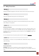
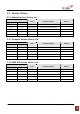
1.3 Version History 1.3.1 Manual Version History List Revision History Approval Ver. Issue Ver. V1.0 Date Item/Description 2013. 10. 18 Initial Version V1.0 V1.1 2013. 10. 31 Component List Modification V1.1 V1.2 2014. 01. 20 Key features Modification Reason 1.3.2 Firmware Version History List Revision History Approval Ver. Issue Ver. V1.0.00 V1.0.00 Date Item/Description 2013. 10. 18 Initial Version Reason 1.3.3 WEB GUI Version History List Revision History Approval Ver.
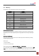
1.4 Glossary The following is a list of abbreviations and terms used in this manual.
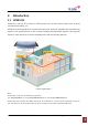
2. Introduction 2.1 APEX1933 APEX1933 is used to fill out areas in APEX systems, such as base station fringe areas, business and industrial building, etc. APEX1933 receives signals from a Small Cell (Femto-Cell, Optional), amplifies and retransmits the signals to the mobile stations. It also receives, amplifies and retransmits signals in the opposite direction.
2.2 APEX1933 Key Features ◈ Design - Digital filtering allows for customized channel selections. - Digital filtering high quality, out of band rejection, and high performance ◈ User friendly design. - Local monitoring and control through the Web GUI interface - Remote monitoring and control through the Web GUI interface. - Reports the status of connection as a function of SNMP regularly and reports an alarm if the event occurred.
No.2, 4 and 8 are for standalone APEX1924/1930/1933 operation. 2.4 Description 2.4.1 Overview APEX1933 USER MANUAL V1.
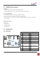
2.4.2 Internal Configuration APEX1933 USER MANUAL V1.
2.4.3 RFU (Radio Frequency Unit) The RFU (RF Unit) is a bi-directional amplifier that sharply filters out unwanted noise. 2.4.4 Duplexer A duplexer is a device that combines two or more signals onto a common channel or medium to increase its transmission efficiency. 2.4.5 PSU (Power Supply Unit) The AC-DC adaptor supplies a steady DC power to the APEX19xx equipment by drawing power from the general in-wall AC outlets. 2.4.
Due to the variations of system layouts and requirements it is not possible to have one procedure that will suffice every installation. You are strongly advised to acquire the services of an RF system designer to calculate your antenna isolation requirements. Ensure that your antennas are at the maximum possible distance apart. Do not place antennas in close proximity to each other; otherwise you will activate the oscillation detection process.
2.4.11 Calculating the Maximum Output Power allowed The regulatory limits for maximum output power are specified in EIRP (equivalent isotro pic radiated power). The EIRP level of a device will be installation dependent and final c onfiguration is the responsiblity of the professional installer. However in general the fin al EIRP can be calculated by adding the gain of the antenna used (specified in dBi) to the output power available at the connector (specified in dBm) minus any cable loss.
3. Mechanical Installation The installation procedure is as follows: • Confirm Items from List • Mounting • Grounding • RF Cable Connection • Power On 3.1 Mounting Step 1 Drill holes directly through the template. Attach the mounting bracket to the wall using provided bolts (16/5*50mm) or extra screws. Step 2 Lean the APEX19xx to hang the topside of the Guide Ring on the mounting bracket, and push toward the wall to mount. APEX1933 USER MANUAL V1.
Step 3 Fix the equipment using the 4 bolts (M6*12mm) provided. Step 4 Fix the equipment using the 2 bolts (M4*8mm) provided. Step 5 Connecting multiple APEX equipments. APEX1933 USER MANUAL V1.
4. Cable Installation 4.1 Cable Connection Step 1: Connect a cable from the donor antenna to the Donor Antenna Port. Step 2: Connect a cable from a equipment’s service antenna to the Sever Antenna Port. APEX1933 USER MANUAL V1.
4.2 Power On ※ Notice: Antenna cables must be installed before connecting AC Power. Step 1: Connect the power cord to the Equipment Step 2: Plug the power cord into a wall outlet. Step 3: Turn the red power button on Step 4: Check if the green LED at the Top turns on. 4.3 Grounding Step 1: A rod on the left side is intended for a building ground. Step 2: Connect the ground cable to the rod. APEX1933 USER MANUAL V1.
5. GUI Operation APEX19xx operates on a customer provided PC based platform with the following system requirements: • Windows® XP or Windows® Vista, Windows 7 • Internet Explorer 6.0(Recommended) or higher. • 128 MB RAM or higher. • Pentium Ⅲ processor or higher. • RJ-45 Cable required. 5.1 GUI Operation Flow Chart APEX1933 USER MANUAL V1.
5.2 Internet Network Setup 5.2.1 Windows 7 (Refer to 5.9 for other versions of Windows) Step 1: Click the Start button and select Control Panel. Step 2: Click Network and Internet. Step 3: Click Network and Sharing Center. Step 4: Click View status of Local Area Connection. Step 5: Click Properties and a caution pop-up Step 6: Select Internet Protocol Version 4 (TCP/IPv4) window will appear. Click OK. and click Properties. APEX1933 USER MANUAL V1.
Step 7: Check Obtain an IP address automatically and click OK. Step 8: Close all windows. 5.3 System Login For APEX19xx operation access, go to Web GUI and Log in. Step 1: Open your Web browser and type http://192.168.0.1 into the URL address box. Then press the Enter key. Step 2: Confirm a User ID and type the password into the password box. Type “operator” for the password and then click OK. Step 3: The pop-up message for the login success will appear. Click OK.
5.4 System Setup When you click Network in the initial screen you can set up User Note, Comment, Ethernet, and time setting. 5.4.1 Time Setting The time will automatically set to your PC time when you click OK. In the above page, you can set system date and time and update time-related information. 5.4.2 Network Setup APEX1933 USER MANUAL V1.
5.4.2.1 SYSTEM • Cascade Code: Type the pre-assigned cascade code. Otherwise, you cannot access the system setup. ¾ Set up for multiple bands Equipment with NCU installed is designated as the master control. The other equipments will connect to the master via RJ 45 cable. The master web GUI will display the other equipments if the connection is successful. 1) Cascade code 1 of SYSTEM in Network setup: Put Direct LAN Cable into Equipment 1 port and connect to NMS port.
• Location Information: Enter the latitude and longitude. You can input values either in Decimal Degrees or Degrees-Minutes-Seconds. [Example] (‘N/S’ | ‘E/W’) ddd.dddddd: (Latitude: N 39.006967 Longitude: W 94.532306) • Refresh Time: Set each refresh time for connecting to Local port and Remote port. 5.4.2.2 ETHERNET SETTING • Ethernet IP Mode/IP Address: Enables you to set a connection mode for the network connected to the APEX19xx remote LAN port.
• Location Information: Type the location information such as the building name, address, city, state, zip code and telephone, and then click Apply. • Donor Site Information: Type the base station’s ID, and then click Apply. • Installer Information: Type the installer information such as the company, name and telephone, Click Apply. 5.4.4 User Comment • User Comment: The user can store up to 50 comments in memory. The length of each comment is limited to 20 characters.
5.5 GUI System Control 5.5.1 System Control APEX1933 USER MANUAL V1.
• Easy Setup is a fast start function. The function measures Isolation, detects input level and assign gain to achieve maximum output power. The function ends with the equipment set to amplify signals in both directions within the confines of the band selection. Before running easy setup, set the center frequency and bandwidth (refer to 4.3.3 part 2). Maximum DL output power requires at least -10dBm input power and sufficient antenna isolation.
• Gain Tracking sets UL gain equal to DL gain. The feature helps maintain forward and reverse link balance. The function control is grayed out when AGC mode is on. • Automatic Gain Control : - In contrast to manual gain control, automatic gain control (AGC) sets gain such that the desired amplifier output level (33dBm) is automatically set. - The user controls gain by adjusting the AGC level. The user may set the level from 0dBm to 33dBm.
5.5.3 Alarm Control • Alarm response time may be set between 0 and 5 minutes. • Alarm Mask allows the user to customize the type of alarms sent to the SNMP server when remote monitoring is in use. 5.5.4 Band Select • Band select sets the digital filter to the center frequency and bandwidth of the local service for which the equipment is intended to amplify. Likewise, all other signals outside of the selected Center Frequency and Bandwidth are rejected.
5.6 GUI System Setup 5.6.1 Easy Setup Step 1: Click Apply after setting Center Frequency and Band Width in use. Step 2: Input AGC Level desired and click Apply. 1) AGC Level 33dBm 2) AGC Level 30dBm Step 3: Easy Setup proceeds to: • Data Initial execution • Isolation Test exeduted • Calculation of Available Maximum Gain by the isolation • DL/UL Path On • AGC On to obtain DL Output Power AGC Level or Maximum Gain 43dB • ASD On APEX1933 USER MANUAL V1.
• AGC Off • Easy setup takes about 2minutes. Click Execute button of Easy Setup Step 4: Click OK. 1) AGC Level 33dBm 2) AGC Level 30dBm Step 5: Setup will automatically begin. This process takes approximately 3minutes. APEX1933 USER MANUAL V1.
Result 1: Constant Maximum DL Output Power 33dBm (AGC Level 33dBm) If the DL input Power ≥ -10dBm Result 2: Constant Maximum DL Output Power 30dBm (AGC Level 30dBm) If the DL input Power ≥ -10dBm APEX1933 USER MANUAL V1.
5.6.2 Manual Gain Setting 5.6.2.1 AGC mode “On” Setting Step 1: Repeat Step 1 through Step 2 Step 2: Isolation Check The Isolation will calculate the Available Maximum Gain which defines the maximum gain to be setup. Click Isolation Step 3: Click OK. Step 4: When below pop-up appears after Isolation is completed, click OK. APEX1933 USER MANUAL V1.
Step 5: AGC must be turned on. AGC automatically assigns gain in accordance with AGC level. Use AGC level to increase or decrease gain. (Gain Offset is a gain differential between DL Output gain and UL output gain.) Ex> AGC Level 33dBm, Gain Offset -3dB → DL Gain 43dB, UL Gain 40dB AGC Level 33dBm, Gain Offset 0dB → DL Gain 43dB, UL Gain 43dB Step 6: Turn on the DL and UL path controls. APEX1933 USER MANUAL V1.
5.6.2.2 AGC mode “Off” setting When you want to set gain value not using Auto Gain control refer to the following. Step 1: For manual gain control AGC must be turned off. Step 2: The user can select any gain value as long as it does over-drive the amplifier or exceed isolation requirements. Gain is automatically limited where conditions do not permit high gain. Select the DL and UL Gain values. Turn on the DL and UL path controls. APEX1933 USER MANUAL V1.
5.7 GUI Status The status page display system, control, and alarm information. When you set any value on the Control page the change will be reflected on Status page. 5.7.1 System • Firmware version and location are displayed under Equipment Information. • The current band setting, set from the control page, is shown in bold font. 5.7.2 Operating • DL Path Monitor displays input from the donor antenna circuit, output power at equipment server antenna port, and downlink amplifier gain.
Alarms shown on the status page will have orange (alarm) or green (normal) background. • Details for alarm events are displayed on the Alarm History page. For corrective action please refer to 6. Troubleshooting section. 5.8 File Update 5.8.1 MCU Firmware Download Step 1. For target, select “MCU“. Choose the correct target slot. If you are not sure, follow the LAN cable from the equipment receiving the update to the host equipment.
Step 3 Click Update. Step 4 When File update message appears and updating completed, go to Log-in page. Log-in and confirm the firmware version has been updated. APEX1933 USER MANUAL V1.
5.8.2 Web GUI Download Step 1 Select WEB in File Update page and click Browse. Step 2 Select Firmware file which has “.web“ filename extension to download. Click Open. Step 3 Click Update. APEX1933 USER MANUAL V1.
Step 4 When File update message appears and updating completed, go to Log-in page. 5.9 Attachment 5.9.1 Internet Network Setting 5.9.1.1 Window XP Step 1: Click the Start button and select My Network places. Step 2: Click View network connections. Step 3: Right-click on the Local Area Connection Step 4: Select Internet Protocol (TCP/IP) and click and select Properties to view the shortcut menu. Properties. APEX1933 USER MANUAL V1.
Step 5: Check Obtain an IP address automatically and click OK. Step 6: Close all widows. 5.9.1.2 Windows Vista Step 1: Click the Start button and select Control panel. Step 3: Click Network and Sharing Center. APEX1933 USER MANUAL V1.2 Step 2: Click Network and Internet Step 4: Click View status of Local Area Connection.
Step 5: Click Properties and a caution pop-up Step 6: Select Internet Protocol Version 4 (TCP/IPv4) window will appear. Click OK. and click Properties. Step 7: Check Obtain an IP address automatically and Click OK. APEX1933 USER MANUAL V1.2 Step 8: Close all windows.
6. Troubleshooting Before contacting your service dealer, refer to the following guidelines. If the APEX1933 equipment does not work normally after completing the following troubleshooting, please contact your local dealer or R-tron America’s Tech support line (1-888-31R-TRON). External alarm lamps on the front of the equipment indicate current condition. Green lamp indicates power to the equipment, yellow indicates caution, and red indicates shut sown 6.
6.2 GUI Alarm Problem Check Point DC Current Solution If the same alarm occurs after reset Power, request technical support. Execute of System Reset (NCU) on Network Setup General Temperature page. If the same alarm occurs request technical support. ASD Heartbeat Check Isolation and DL/UL Input power.. Check the connection of the Remote NMS Cable. Check the interval of Heartbeat on the WEB GUI DL Input alarm can be the result of low signal level DL Input Power from the donor antenna circuit.
6.3 Communication Alarm When you cannot login to the web GUI. Solution 1. Click My Network places Æ View network 2. Right-click on the Local Area Connection and then connections. Right-click on the Wireless click Disable. After clicking Disable, click Enable Network Connection and then click Disable. again. 3. Double click the Local Area Connection and then click the Support tab Æ Repair. APEX1933 USER MANUAL V1.
Solution 4. Open the Internet Browser, select Tools Æ Internet Options. 5. Click Start and select Run. Type “ping 192.168.0.1-t” and click OK. Click Delete Files in the Temporary Internet files section. APEX1933 USER MANUAL V1.
7. Specifications 7.
7.2 Environmental Specification Specification Parameter Operating Temp -10˚C~50˚C (14˚F~122˚F) Humidity 5% ~ 95%RH Cooling method Convection. Environmental 7.3 Electrical Specification Parameter Specification Voltage AC 85-264V Current +24V/6.5A (150W) Frequency 50/60(47-63)Hz 7.4 Mechanical Specification Parameter Specifications RF connectors N-female x 2 Dimensions (WxHxD) 9.35 * 16.8 * 5.67 Inch 242 * 426 * 144 mm Weight 44.09 lb 20 Kg max APEX1933 USER MANUAL V1.
8. Appendix 8.1 US PCS Channel APEX1933 USER MANUAL V1.
8.2 Warranty LIMITED WARRANTY This product, as supplied and distributed by R-tron, in the original carton, is warranted by R-tron against manufacturing defects in materials and workmanship for a limited warranty period of: Five (5) Year Parts and Labor This limited warranty begins on the original date of purchase, and is valid only on products purchased and used in the United States.
1. Call Tech Support for troubleshooting. 2. If the device has hardware problem, R-tron will replace it if it is within warranty. A RMA number will be issued for the return. 3. R-tron will ship the replacement unit with a return shipping label. 4. The customer must return the product using the original packaging, including all accessories and/or parts. APEX1933 USER MANUAL V1.