APEX 1924 User’s Manual Please read this manual before operating this product. After you finish reading this manual, store it in a safe place for future reference.
Notice Trademark R-tron is a registered trademark of R-tron Inc. Other products and company names mentioned here in this manual might be trademarks or trade names of their respective owners. Copyright Copyright © R-tron Inc. 2000-2010 All Rights Reserved Any reproduction, distribution, or revisions of any or all portions of this manual is prohibited without written permission from R-tron Inc. Notice This document describes the specifications, installation, and operation of the APEX 1900-24 repeater.
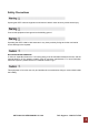
Safety Precautions Opening the APEX 1900-24 equipment could result in electric shock and may cause severe injury. Connect the equipment frame ground to the building ground. Operating the APEX 1900-24 with antennas in very close proximity facing each other can lead to severe damage to the repeater. RF EXPOSURE INFORMATION A minimum separation distance of 7.9 inches (20cm) must be maintained between the user and the external antenna of the repeater to satisfy FCC RF exposure requirements.
Manual Version History List Revision History Approval Ver. Issue Ver. Date Item/Description Reason Item/Description Reason Item/Description Reason Firmware Version History List Revision History Approval Ver. Issue Ver. Date WEB GUI Version History List Revision History Approval Ver. Issue Ver. Date APEX 1900-24 USER MANUAL V1.0.
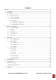
Contents Glossary ............................................................................................................................................... 4 1. Introduction .................................................................................................................................. 4 2. Description .................................................................................................................................... 5 2.1 Main Unit Overview ......................
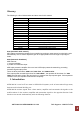
Glossary The following is a list of abbreviations and terms used in this manual.
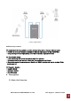
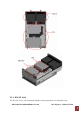
< Basic Organization > APEX1924 Key Features ◈ Design(Each BDA is possible to service selected channels by the user within a band.) - Possible to select any channel combination within a band caused by the Digital Filter. - Using the Digital Filter: High quality, out of band rejection, high performance ◈ User friendly design.
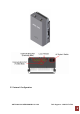
2.2 Internal Configuration APEX 1900-24 USER MANUAL V1.0.
2.2.1 RFU (RF Unit) The RFU (RF Unit) is a bi-directional amplifier that sharply filters out unwanted noise. APEX 1900-24 USER MANUAL V1.0.
2.2.2 Duplexer A duplexer is a device that combines two or more signals onto a common channel or medium to increase its transmission efficiency. 2.2.3 PSU (Power Supply Unit) The AC-DC adaptor supplies a steady DC power to the APEX1924 equipment by drawing power from the general in-wall AC outlets. Specification Item Environmental Specification Operating Temp -10˚C~50˚C (14˚F~122˚F) Humidity 20%~90%RH Cooling method Convection. Voltage Current Frequency AC 85-264V +24V/6.5A (150W) 50/60(47-63) 2.
• Mounting • Grounding • RF Cable Connection • Power On 3.1 Check List of Items Index Items Quantity 1 Repeater 1 2 AC Cable 1 3 LAN Cable 1 4 Anchor Bolt 4 5 Quick Installation Guide 1 6 User’s Manual 1 3.2 Mounting Step 1: Drill holes directly through the template. and attach the mounting bracket to the wall using provided bolts or extra screws. APEX 1900-24 USER MANUAL V1.0.
Step 2: Lean the APEX1924 to hang the topside of the Guide Ring on the mounting bracket, and push toward the wall to mount. APEX 1900-24 USER MANUAL V1.0.
Step 3: Fix the APEX1924 using the 4 screws provided. Step 4: Example APEX 1900-24 USER MANUAL V1.0.
3.3 Grounding A rod on the left side is intended for a building ground. Connect the ground cable to the rod. 3.4 Cable Connection Step 1: Connect a cable from the donor antenna to the Donor Antenna Port. Step 2: Connect a cable from a repeater’s service antenna to the Sever Antenna Port. APEX 1900-24 USER MANUAL V1.0.
3.5 Power On Step 1: Connect the power cord. Step 2: Plug the power cord into a wall outlet. Step 3: Check if the green LED at the Top turns on. APEX 1900-24 USER MANUAL V1.0.
4. Operation 4.1 System Requirements APEX1900-24 operates on a customer provided PC based platform with the following system requirements: • Windows® XP or Windows® Vista, Windows 7 • Internet Explorer 6.0(Recommended) or higher • 128 MB RAM or higher • Pentium Ⅲ processor or higher • RJ-45 jack required 4.2 Network Setup 4.2.1 Windows XP Step 1: Click the Start button and select My Network Places. APEX 1900-24 USER MANUAL V1.0.
Step 2: Click View network connections. Step 3: Right-click on the Local Area Connection and select Properties to view the shortcut menu. Step 4: Select Internet Protocol (TCP/IP) and click Properties. APEX 1900-24 USER MANUAL V1.0.
Step 5: Check Obtain an IP address automatically and click OK. Step 6: Close all widows. 4.2.2 Windows Vista Step 1: Click the Start button and select Control Panel. APEX 1900-24 USER MANUAL V1.0.
Step 2: Click Network and Internet. Step 3: Click Network and Sharing Center. APEX 1900-24 USER MANUAL V1.0.
Step 4: Click View status of Local Area Connection. Step 5: Click Properties and a caution pop-up window will appear. Click OK. APEX 1900-24 USER MANUAL V1.0.
Step 6: Select Internet Protocol Version 4 (TCP/IPv4) and click Properties. Step 7: Check Obtain an IP address automatically and click OK. Step 8: Close all windows. APEX 1900-24 USER MANUAL V1.0.
4.2.3 Windows 7 Step 1: Click the Start button and select Control Panel. Step 2: Click Network and Internet. APEX 1900-24 USER MANUAL V1.0.
Step 3: Click Network and Sharing Center. Step 4: Click View status of Local Area Connection. APEX 1900-24 USER MANUAL V1.0.
Step 5: Click Properties and a caution pop-up window will appear. Click OK. Step 6: Select Internet Protocol Version 4 (TCP/IPv4) and click Properties. APEX 1900-24 USER MANUAL V1.0.
Step 7: Check Obtain an IP address automatically and click OK. Step 8: Close all windows. APEX 1900-24 USER MANUAL V1.0.
4.3 System Login Step 1 Open your Web browser and type http://192.168.0.1 into the URL address box. Then press the Enter key. Step 2 The login screen will appear. Type “operator” for the ID and “rtron” for the password and then Click OK. Step 3 The pop-up message for the login success will appear. Click OK. Step 4 When the login process is complete, the initial screen will appear. APEX 1900-24 USER MANUAL V1.0.
4.3.1 Network ① Clock In the above page, you can set device time and update time-related information. Click the “set time” button to save your settings. ② Network Set-up ¾ SYSTEM APEX 1900-24 USER MANUAL V1.0.
• Cascade Code: Type the pre-assigned cascade code. Otherwise, you cannot access the system setup. • Location Information: Enter the latitude and longitude. You can input values either in Decimal Degrees or Degrees-Minutes-Seconds. [Example] (‘N/S’ | ‘E/W’) ddd.dddddd: (Latitude: N 39.006967 Longitude: W 94.532306) • Product Information: This is for manufacturer use only. Do not change this value.
• Location Information: Type the location information such as the building name, address, city, state, zip code and telephone, and then click Apply. • Donor Site Information: Type the base station’s ID, and then click Apply. • Installer Information: Type the installer information such as the company, name and telephone, Click Apply. ④ User Comment • User Comment: You can store up to 50 comments in memory. The length of each comment is limited to 20 characters.
4.3.2 Status 4.3.3 Control APEX 1900-24 USER MANUAL V1.0.
4.3.4 File Update 4.3.5 Alarm History Alarm history page allows you to record alarm information of each unit. Up to 300 lists can be accommodated. APEX 1900-24 USER MANUAL V1.0.
5. Troubleshooting Before contacting your service dealer, please make sure you refer to the following guidelines. If the APEX1900-24 repeater does not work normally after completing the following troubleshooting, please contact your local dealer or R-tron America’s Tech support line (1-88831R-TRON). The alarm information is displayed by the LED lights on the APEX1900-24 repeater. Problem Cause No LED on Solution Check the power cord for secure connection Check if the power is ON.
Problem Cause Solution Cannot communicate 1. Click My Network places Æ View network with the CAT-5 DAS connections. Right-click on the Wireless Network Connection and then click Disable. APEX 1900-24 USER MANUAL V1.0.
Problem Cause Solution 2. Right-click on the Local Area Connection and then click Disable. After clicking Disable, click Enable again. 3. Double click the Local Area Connection and then click the Support tab Æ Repair. APEX 1900-24 USER MANUAL V1.0.
Problem Cause solution 4. Open the Internet Browser and then select Tools Æ Internet Options. Click Delete Files button in the Temporary Internet files section. APEX 1900-24 USER MANUAL V1.0.
Problem Cause Solution 5. Click Start and select Run. Type “ping 192.168.0.1-t” and click OK. APEX 1900-24 USER MANUAL V1.0.
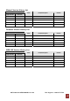
6. Specifications 6.1 RF Characteristics Electrical Specifications Parameter Down-Link Up-Link Frequency Range 1930 - 1995 MHz (65M B.W) 1850 - 1915 MHz (65M B.
6.2 Mechanical Specification Parameter Specifications RF connectors N-female x 2 Dimensions (WxHxD) Weight 9.35 * 16.8 * 5.67 Inch 242 * 426 * 144 mm 44.09 lb 20 Kg max APEX 1900-24 USER MANUAL V1.0.
7. Appendix USPCS Channel APEX 1900-24 USER MANUAL V1.0.
Warranty LIMITED WARRANTY This product, as supplied and distributed by R-tron, in the original carton, is warranted by R-tron against manufacturing defects in materials and workmanship for a limited warranty period of: Five (5) Year Parts and Labor This limited warranty begins on the original date of purchase, and is valid only on products purchased and used in the United States.
Return Material Authorization(RMA) Procedure The return and exchange of products are not allowed without prior approval from R-tron America, Inc. Please follow the exchange procedure below. 1. Call Tech Support for troubleshooting. 2. If the device has a hardware problem, R-tron will replace it if it is within warranty. A RMA number will be issued for the return. 3. R-tron will ship the replacement unit with a return shipping label. 4.