
Installation guide

C-36
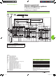
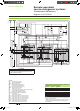
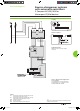
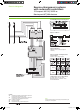
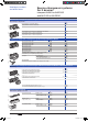
Electrical diagrams
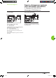
Electrical interlocking with lockout after a fault
DB101765
ATTENTION
(1) Not to be wired for the “without lockout after a fault” solution.
(2) Not to be wired on xed version.
(3) Prefabricated wiring supplied.
The diagram shows the electrical wiring for circuit breakers.
When wiring the SDE with switch-disconnectors, connect
wire BK to terminal 82.
Legends
QN “Normal”
source Masterpact NT or NW
QR “Replacement” source Masterpact NT or NW
MCH spring-charging
motor
MX standard opening voltage release
XF
standard closing voltage release
OF... breaker
ON/OFF indication contact
SDE1 “fault-trip”
indication contact
PF “ready-to-close” contact
CE1 “connected-position”
indication contact (carriage switch)
CH “springs charged” indication contact
IVE
electrical interlocking and terminal block unit
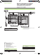
States permitted by mechanical interlocking system
Normal Replacement
0 0
1 0
0 1
Wiring colour codes
Note:
diagram shown with circuit breakers in connected position, open,
charged, and ready to close.
RD GN BK VT YE GY WH BN
red green black violet yellow grey white brown
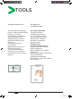
Source-changeover systems
with automatic controllers
2 Masterpact NT or NW devices
Diagram no. 51156903
Livre 1.indb 36 08/10/2008 18:40:14