
Installation guide

C-34
Electrical diagrams
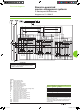
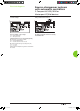
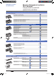
Source-changeover system with UA controller
Load shedding and genset management
DB101757
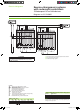
DB101758
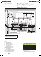
Transfer conditions
DB101759
Terminals 20 and 21:
additional control contact (not part of
controller).
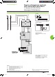
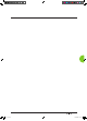
Tests on “Normal” and “Replacement”
source voltages
“Normal” source voltage UN test
DB101761
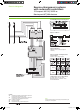
“Replacement” source voltage UR test
The single-phase check for UR is
implemented across terminals 1 and 5
of circuit breaker Q2.
Legends
Q1 circuit breaker supplying and protecting the automatic-
control
circuits for the “Normal” source
Q2 circuit
breaker supplying and protecting the automatic-
control circuits for the “Replacement” source
ACP auxiliaries
control plate
UA automatic
controller
IVE electrical
interlocking and terminal block unit
Note:
diagram shown with circuits de-energised, circuit breakers open
and relays in normal position.
Source-changeover systems
with automatic controllers
2 Compact NS100/1600 or
Masterpact NT/NW devices
Livre 1.indb 34 08/10/2008 18:40:11