
Installation guide

C-32
Electrical diagrams
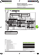
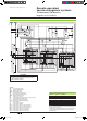
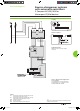
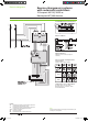
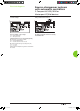
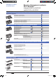
2 sources and 1 coupling: automatic-control system with lockout after a fault
DB101749
ATTENTION
The diagram shows the electrical wiring for circuit breakers.
When wiring the SDE with switch-disconnectors, connect
the SDE to terminals 81 and 84.
Legends
QS... “Source”
Masterpact NW
QC “Coupling” Masterpact NW
MCH spring-charging
motor
MX standard opening voltage release
XF
standard closing voltage release
OF... breaker
ON/OFF indication contact
SDE1 “fault trip” indication contact
PF
“ready-to-close” contact
CE...
“connected-position” indication contact (carriage switch)
CH “springs charged” indication contact
F1
auxiliary power supply circuit breaker
F2/F3 circuit
breaker (high breaking capacity)
S1 control switches
S2
source selection switches
KA1 auxiliary
relays with 10 to 180 sec. time delay
KA2 auxiliary
relays with 0.1 to 30 sec. time delay
KA3 auxiliary
relays with 10 to 180 sec. time delay
KA4 auxiliary
relays with 0.1 to 30 sec. time delay
KA5 auxiliary
relays with 0.25 sec. time delay
KA6 auxiliary
relays with 0.25 sec. time delay
KA7 auxiliary
relays with 0.25 sec. time delay
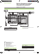
States permitted by mechanical interlocking system
and with associated automatism
Source 1 Source 2 Coupling
0 0 0
1 1 0
1 0 1
0 1 1
1 0 0
0 1 0
0 0 1
Note:
diagram shown with circuit breakers in connected position, open,
charged, and ready to close.
Auxiliary power supply = supply voltage of auxiliary relays (KA...)
= supply voltage of electrical auxiliaries (electrical operation,
MCH, MX, MN...).
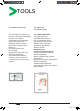
Remote-operated
source-changeover systems
3 Masterpact NW devices
Diagram no. 51156914
Livre 1.indb 32 08/10/2008 18:40:09