
Installation guide

C-28
Electrical diagrams
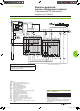
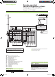
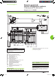
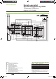
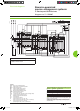
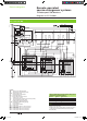
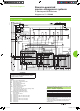
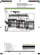
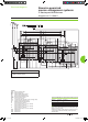
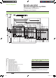
3 sources with only 1 device closed: electrical interlocking without lockout after a fault
DB101741
Legends
QS... “Source”
Masterpact NW
MCH spring-charging
motor
MX standard opening voltage release
XF standard
closing voltage release
OF... breaker
ON/OFF indication contact
PF “ready-to-close”
contact
CE... “connected-position”
indication contact (carriage switch)
CH “springs charged” indication contact
F1
auxiliary power supply circuit breaker
t1 order
for transfer to “Source 1”
(QS1 closing time delay = 0.25 sec. minimum)
t2 order for transfer to “Source 2”
(QS2
closing time delay = 0.25 sec. minimum)
t3 order
for transfer to “Source 3”
(QS3 closing time delay = 0.25 sec. minimum)
States permitted by mechanical interlocking system
Source 1 Source 2 Source 3
0 0 0
1 0 0
0 1 0
0 0 1
Note:
diagram shown with circuit breakers in connected position, open,
charged, and ready to close.
Auxiliary power supply = supply voltage of auxiliary relays (KA...)
= supply voltage of electrical auxiliaries (electrical operation,
MCH, MX, MN...).
Remote-operated
source-changeover systems
3 Masterpact NW devices
Diagram no. 51156910
Livre 1.indb 28 08/10/2008 18:40:04