
Installation guide

C-22
Electrical diagrams
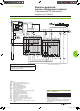
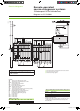
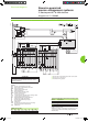
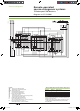
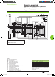
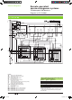
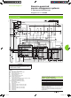
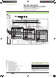
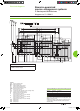
Automatic-control system for permanent replacement source with lockout after a fault (with MN)
DB112557
ATTENTION
(1) Not to be wired for the “without lockout after a fault” solution.
(2) Not to be wired on xed version.
(3) Prefabricated wiring supplied.
The diagram shows the electrical wiring for circuit breakers.
When wiring the SDE with switch-disconnectors, connect
wire BK to terminal 82.
Legends
QN “Normal”
source Masterpact NT or NW
QR “Replacement” source Masterpact NT or NW
MCH
spring-charging motor
XF
standard closing voltage release
MN
undervoltage release
OF... breaker
ON/OFF indication contact
SDE1 “fault-trip”
indication contact
PF “ready-to-close”
contact
CE1 “connected-position”
indication contact (carriage switch)
CH “springs charged” indication contact
IVE
electrical interlocking and terminal block unit
F1
auxiliary power supply circuit breaker
F2
circuit breaker (high breaking capacity)
S1
control switches
KA1 auxiliary
relays
KA2 auxiliary
relays
KA3 auxiliary relays
States permitted by mechanical interlocking system
Normal Replacement
0 0
1 0
0 1
Note:
diagram shown with circuit breakers in connected position, open,
charged, and ready to close.
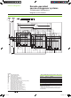
Auxiliary power supply = supply voltage of auxiliary relays (KA...)
= supply voltage of electrical auxiliaries (electrical operation,
MCH, MX, MN...).
Wiring colour codes
RD GN BK VT YE GY WH BN
red green black violet yellow grey white brown
Remote-operated
source-changeover systems
2 Masterpact NT or NW devices
Diagram no. 51156904
Livre 1.indb 22 08/10/2008 18:39:56