
Installation guide

C-16
Electrical diagrams
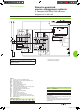
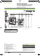
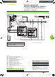
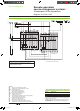
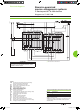
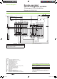
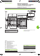
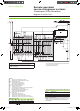
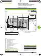
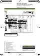
Electrical interlocking with lockout after a fault and emergency off by undervoltage release
DB101713
ATTENTION
(1) Not to be wired on xed version.
The diagram shows the electrical wiring for circuit breakers.
When wiring the SDE with switch-disconnectors, connect
the SDE to terminals 81 and 84.
Legends
QN “Normal”
source Masterpact NT or NW
QR “Replacement” source Masterpact NT or NW
MCH spring-charging
motor
MX standard opening voltage release
XF
standard closing voltage release
MN
undervoltage release
OF... breaker
ON/OFF indication contact
SDE1 “fault-trip”
indication contact
PF “ready-to-close” contact
CE1 “connected-position”
indication contact (carriage switch)
CH “springs charged” indication contact
F1
auxiliary power supply circuit breaker
BP emergency off button with latching
S1
control switches
KA3 auxiliary
relay
ON “Normal” source opening order
OR
“Replacement” source opening order
FN
“Normal” source closing order (0.25 second delay)
FR
“Replacement” source closing order (0.25 second delay)
States permitted by mechanical interlocking system
Normal Replacement
0 0
1 0
0 1
Note:
diagram shown with circuit breakers in connected position, open,
charged, and ready to close.
Auxiliary power supply = supply voltage of auxiliary relays (KA...)
= supply voltage of electrical auxiliaries (electrical operation,
MCH, MX, MN...).
Remote-operated
source-changeover systems0
2 Masterpact NT or NW devices
Diagram no. 51201141
Livre 1.indb 16 08/10/2008 18:39:50