
Installation guide

C-11
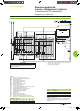
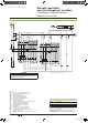
Electrical diagrams
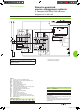
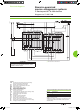
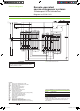
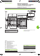
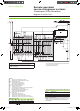
Electrical interlocking by IVE with emergency off by undervoltage release
DB112556
ATTENTION
(1) Not to be wired on xed version.
(2) Prefabricated wiring supplied.
The diagram shows the electrical wiring for circuit breakers.
When wiring the SDE with switch-disconnectors, connect
wire BK to terminal 82.
Legends
QN “Normal”
source Compact NS630b to 1600
QR “Replacement”
source Compact NS NS630b to 1600
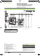
MCH spring-charging
motor
MX standard opening release
XF
standard closing release
OF... breaker
ON/OFF indication contact
SDE1 “fault-trip”
indication contact
CE1 “connected-position”
indication contact (carriage switch)
F1 auxiliary power supply circuit breaker
IVE
electrical interlocking and terminal block unit
MN
undervoltage release
BP emergency off button with latching
KA3 auxiliary
relay
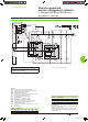
ON “Normal” source opening order
OR
“Replacement” source opening order
FN
“Normal” source closing order (0.25 second delay)
FR
“Replacement” source closing order (0.25 second delay)
MT Motor
Mechanism
States permitted by mechanical interlocking system
Normal Replacement
0 0
1 0
0 1
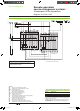
Note:
after a fault trip, the breaker must be reset manually by pressing
its reset button.
Diagram shown with circuit breakers in connected position, open,
charged, and ready to close.
Auxiliary power supply = supply voltage of auxiliary relays (KA...)
= supply voltage of electrical auxiliaries (electrical operation,
MCH, MX, MN...).
Wiring colour codes
RD GN BK VT YE GY WH BN
red green black violet yellow grey white brown
Remote-operated
source-changeover systems
2 Compact NS630b/1600 devices
Diagram no. 51201185
Livre 1.indb 11 08/10/2008 18:39:46