
Installation guide


C-5
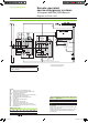
Electrical diagrams
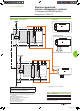
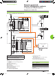
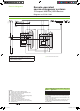
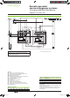
Source-changeover system without automatic-control system
With emergency off by MX release and automatic reset
DB101691
Automatic reset
ATTENTION
(1) Prefabricated wiring supplied
(2) This source can be:
b the source present in the case of voltage monitoring
b an independent source.
In this case, the MX release must be protected.
(3) The reset orders must be delayed by 0.3 seconds.
The diagram shows the electrical wiring for circuit breakers.
When wiring the SDE with switch-disconnectors, reverse
the wires connected to terminals 82 and 84.
Legends
QN
“Normal” source Compact NS equipped with motor
mechanism
QR
“Replacement” source Compact NS equipped with motor
mechanism
SDE “fault-trip”
indication contact
OF2 breaker
ON/OFF indication contact
MX shunt release
MT
motor mechanism
IVE
electrical interlocking and terminal block unit
KA1 time-delayed
auxiliary relays
KA2 time-delayed
auxiliary relays
F1 auxiliary power supply circuit breaker
F2
auxiliary power supply circuit breaker
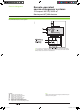
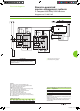
States permitted by mechanical interlocking system
Normal Replacement
0 0
1 0
0 1
Note:
after a fault trip, the breaker must be reset manually by pressing
its reset button.
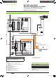
Diagram shown with circuits de-energised, circuit breakers open
and relays in normal position.
Remote-operated
source-changeover systems
2 Compact NS100/630 devices
Diagram no. 51201179
Livre 1.indb 5 08/10/2008 18:39:41