
Installation guide

B-6
Dimensions
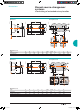
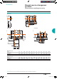
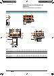
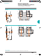
Assembly for INS250 100 to 250 A / Assembly for INS320/400/500/630
Dimensions
DB101625
DB101626
Front-panel cutout
DB101627
Dimensions (mm)
Type A B C D E F G H I J K L M N
INS250 60.4 1
30.4 296 68 136 131 61.8 279.3 42 84 156 186.5 5.5 50
INS320/630 82.5 175 395 1
02.5 205 155 87 383.7 64 128 210 213 8 50
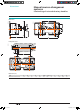
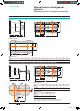
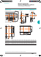
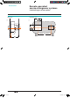
Dimensions of the complete source-changeover assembly with an extended handle
DB101650
DB101651
DB107743
Dimensions (mm)
Type A B C E K L M N
INS250
INV100/250
60.4 1
30.4 295 136 156 138.5 631 50
INS320/630
INV320/630
8
2.5 175 395 2
05 210 162.5 658 75
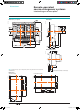
Dimensions (mm)
Type P Mmax Mmin Q
INS250
INV100/250
1
00 567.5 1
95 64
INS320/630
INV320/630
1
50 593 22
0.5 64
Note: Lines X and Y indicate the axes of symmetry of the switch-disconnector.
Reference plane Z corresponds to the back of the switch-disconnector.
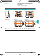
Manual source-changeover
systems
Complete source-changeover assembly
Livre 1.indb 6 08/10/2008 18:39:20