
Installation guide

A-18
Functions
and characteristics
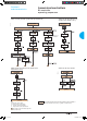
By combining a remote-operated source-changeover
system with an integrated BA
or UA automatic controller, it is possible to
automatically control source transfer according to user-
selected sequences.
These controllers can be used on source-changeover
systems comprising 2 circuit breakers.
For source-changeover systems comprising 3 circuit
breakers, the automatic control diagram must be
prepared by the installer as a complement to to
diagrams provided in the “electrical diagrams” section
of this catalogue.
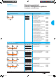
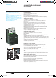
Controller BA UA
Compatible circuit breakers All Compact NS and
Masterpact circuit breakers
4-position switch
Automatic operation b b
Forced operation on “Normal” source b b
Forced operation on “Replacement” source b b
Stop (both “Normal” and “Replacement” sources off) b b
Automatic operation
Monitoring of the “Normal” source and automatic transfer b b
Generator set startup control b
Delayed shutdown (adjustable) of generator set b
Load shedding and reconnection of non-priority circuits b
Transfer to the “Replacement” source if one of the phases
of the “Normal” phase is absent
b
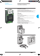
Test
By opening the P25M circuit breaker supplying the controller b
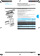
PB100855
By pressing the test button on the front of the controller b
Indications
Circuit breaker status indication on the front of the controller:
on, off, fault trip
b b
Automatic mode indicating contact b b
Other functions
Selection of type of “Normal” source
(single-phase or three-phase)
(1)
b
Voluntary transfer to “Replacement” source (e.g. energy
management commands)
b b
During peak-tariff periods (energy management commands)
forced operation on “Normal” sourceif “Replacement” source not
operational
b
Additional contact (not part of controller).
Transfer to “Replacement” source only if contact is closed. (e.g.
used to test the frequency of UR).
b b
BA controller. Setting of maximum startup time for the replacement source b
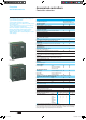
Options
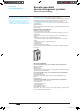
PB100856
Communication option
Power supply
Control voltages
(2)
110 V b b
220 to 240 V 50/60 Hz b b
380 to 415 V 50/60 Hz
and 440 V 60 Hz
b b
Operating thresholds
Undervoltage 0.35 Un y voltage y 0.7 Un b b
Phase failure 0.5 Un y voltage y 0.7 Un b
Voltage presence voltage u 0.85 Un b b
IP degree of protection (EN 60529) and IK degree of protection against
external mechanical impacts (EN 50102)
Front IP40 b b
Side IP30 b b
Connectors IP
20 b b
UA controller. Front IK07 b b
Characteristics of output contacts (dry, volt-free contacts)
Rated thermal current (A) 8
Minimum load 10 mA at 12 V
Output contacts:
Position of the Auto/Stop switch b b
Load shedding and reconnection order b
Generator set start order. b
AC DC
Utilisation category (IEC 947-5-1) AC12 AC13 AC14 AC15 DC12 DC13
Operational current (A) 24 V 8 7 5 5 8 2
48 V 8 7 5 5 2 -
110 V 8 6 4 4 0.6 -
220/240 V 8 6 4 3 - -
250 V - - - - 0.4 -
380/415 V 5 - - - - -
440 V 4 - - - - -
660/690 V - - - - - -
(1) For example, 220 V single-phase or 220 V three-phase.
(2) The controller is powered by the ACP auxiliaries control plate. The same voltage must be used
for the ACP plate, the IVE unit and the circuit-breaker operating mechanisms. If this voltage is the
same as the source voltage, then the “Normal” and “Replacement” sources can be used directly
for the power supply. If not, an isolation transformer must be used.
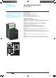
Associated controllers
Controller selection
Livre 1.indb 18 08/10/2008 18:38:59