English Original instructions SERVICE MANUAL FOR TRAVELING INVERTER Service Manual for DMCS 022F - - - - SUPDOC_SM_DMCS0550100-0 PS02379 25.3.2010 SUPDOC_SM_DMCS055-0.ORD 25.3.
R&M Materials Handling, Inc. 4501 Gateway Boulevard Springfield, Ohio 45502 P.: (937) 328-5100 FAX: (937) 325-5319 Table of content 1 DESCRIPTION OF THE INVERTER .................................................................................................. 3 1.1 Connections............................................................................................................................................ 3 1.2 Technical characteristics ..........................................................
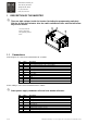
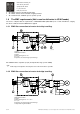
R&M Materials Handling, Inc. 4501 Gateway Boulevard Springfield, Ohio 45502 P.: (937) 328-5100 FAX: (937) 325-5319 1 DESCRIPTION OF THE INVERTER There are high voltages inside the inverter (including the programming switches). Wait for at least three minutes after the supply voltage has been switched off before any service actions. 1 1.Control terminal X1 2.Power terminal X2 3.Programming switches 4.Leds 1.
R&M Materials Handling, Inc. 4501 Gateway Boulevard Springfield, Ohio 45502 P.: (937) 328-5100 FAX: (937) 325-5319 Standard duty resistor must be disconnected when heavy duty resistor DMHR01F90 is connected to terminals R+ and R− −. 1.2 Technical characteristics Technical data Power range Supply voltage Nominal supply frequency Nominal current Digital control Max output voltage Control voltage range 2.2 kW 380 - 480 VAC +/-10% 48 – 62 Hz 5.
R&M Materials Handling, Inc. 4501 Gateway Boulevard Springfield, Ohio 45502 P.: (937) 328-5100 FAX: (937) 325-5319 S4 = Motor frequency and IR-compensation S5 = Motor current, fast deceleration, stopping method S6 = Control mode, slowdown speed, speed2, speed3 1.6 The EMC requirements (Not in use for deliveries in USA/Canada) The device complies with the requirements of EN61800-3:2004 (IEC61800-3) for second environment, category C3, when a dedicated external EMC filter is applied. 1.6.
R&M Materials Handling, Inc. 4501 Gateway Boulevard Springfield, Ohio 45502 P.: (937) 328-5100 FAX: (937) 325-5319 KC-330-00 includes capacitors (4*1µF) and input ferrite rings (3 x EF 32008). 6/14 Ferrite rings and capacitors must be placed as near the inverter as possible. R&M Materials Handling, Inc. reserves the right to alter or amend the above information without notice.
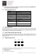
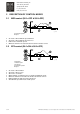
R&M Materials Handling, Inc. 4501 Gateway Boulevard Springfield, Ohio 45502 P.: (937) 328-5100 FAX: (937) 325-5319 2 DESCRIPTION OF CONTROL MODES 2.1 MS2-control (S6-1=OFF & S6-2=OFF) c_coms2a A. Pushbutton position B. Speed S1 means “drive minimum speed forward” S2 means “drive minimum speed reverse” HSP means “maximum speed” When S1 and S2 or are not active the inverter decelerates to zero 2.2 EP2-control (S6-1=ON & S6-2=OFF) c_coep2a 0. Decelerate 1. Maintain speed 2. Accelerate A.
R&M Materials Handling, Inc. 4501 Gateway Boulevard Springfield, Ohio 45502 P.: (937) 328-5100 FAX: (937) 325-5319 2.3 EP3-control (S6-1=OFF & S6-2=ON) c_coep3a 0. Decelerate 1. Minimum speed 2. Maintain speed 3. Accelerate A. Pushbutton position B. Speed S1 means “drive minimum speed forward” S2 means “drive minimum speed reverse” AP means “accelerate” HOLD means “hold speed” When S1 and S2 are not active the inverter decelerates to zero At maximum speed AP means “hold speed” 2.
R&M Materials Handling, Inc. 4501 Gateway Boulevard Springfield, Ohio 45502 P.: (937) 328-5100 FAX: (937) 325-5319 3 FAULT CODES, TROUBLESHOOTING There are high voltages inside the inverter (including the programming switches). Wait for at least three minutes after the supply voltage has been switched off before any service actions. When the inverter detects a fault situation it stops running and starts signalling the fault code by blinking the indication leds (green and red).
R&M Materials Handling, Inc. 4501 Gateway Boulevard Springfield, Ohio 45502 P.: (937) 328-5100 FAX: (937) 325-5319 1 PROGRAMMING OF THE APPLICATION PARAMETERS m Check that he wiring and the mechanical performance of the machinery is suitable for the selected application parameters. 3.1 Minimum speed, maximum speed and ramp time The adjustment ranges of maximum and minimum speed depend on the selected motor nominal frequency.
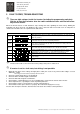
R&M Materials Handling, Inc. 4501 Gateway Boulevard Springfield, Ohio 45502 P.: (937) 328-5100 FAX: (937) 325-5319 3.1.2 Acceleration and deceleration ramp Acceleration and deceleration ramps are set by switch S3 as follows: Switch S3 -1 -2 1 0 0 1 0 0 0 0 0 0 1 0 1 1 0 0 1 1 1 1 1 0 1 0 0 1 0 1 Ramp time (sec) -3 0 0 0 1 0 0 0 1 1 0 1 1 1 0 -4 0 0 0 0 1 1 0 1 0 1 1 0 1 1 1.5 2.0 2.5 3.0 3.5 4.0 4.5 5.0 5.5 6.0 6.5 7.0 7.5 8.0 It is possible to reduce the deceleration ramp time by 30% if necessary.
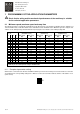
R&M Materials Handling, Inc. 4501 Gateway Boulevard Springfield, Ohio 45502 P.: (937) 328-5100 FAX: (937) 325-5319 MS2 S2 HSP S12 S22 DI2 DI3 DI4 DI5 EP2 S2 AP S11 S21 EP3 S2 HOLD AP S11/S21 MS4 S2 SP2 SP3 HSP Description of the control signals: S1 AP S11 S12 SP2 HSP S2 HOLD S21 S22 SP3 3.
R&M Materials Handling, Inc. 4501 Gateway Boulevard Springfield, Ohio 45502 P.: (937) 328-5100 FAX: (937) 325-5319 2 PROGRAMMING OF THE MOTOR PARAMETERS The motor parameters are set by switches S4 and S5 according to the following table. Only the most common motor types are shown in the table. Settings for other motors can be defined when motor nominal frequency, voltage, current and the IR-rate are known.
R&M Materials Handling, Inc. 4501 Gateway Boulevard Springfield, Ohio 45502 P.