English Original instructions SERVICE MANUAL FOR TRAVELING INVERTER Service Manual for DMCS 007F - - - - DOC_SM_DMCS0190100-0 PS02379 16.11.2010 SUPDOC_SM_DMCS019-0.ORD 16.11.
R&M Materials Handling, Inc. 4501 Gateway Boulevard Springfield, Ohio 45502 P.: (937) 328-5100 FAX: (937) 325-5319 Table of contents 1 DESCRIPTION OF THE INVERTER .................................................................................................. 3 1.1 Connections............................................................................................................................................ 3 1.2 Technical characteristics .........................................................
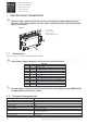
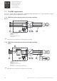
R&M Materials Handling, Inc. 4501 Gateway Boulevard Springfield, Ohio 45502 P.: (937) 328-5100 FAX: (937) 325-5319 1 DESCRIPTION OF THE INVERTER There are high voltages inside the inverter (including the programming switches). Wait for at least three minutes after the supply voltage has been switched off before any service actions. DMCS007 1. Terminal X1 2. Red led (fault) 3. Green led (ok) 4. Programming switches c_fcmo1b 1.
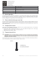
R&M Materials Handling, Inc. 4501 Gateway Boulevard Springfield, Ohio 45502 P.: (937) 328-5100 FAX: (937) 325-5319 Technical data Humidity Degree of protection Dimensions (WxHxD) Altitude DMCS007 95% N.C. (without dripping) Frequency converter + cover (IP20) 133x92x60mm Output current must be reduced 1 % for every 100 m over 1000 m. For altitudes over 3000 m, manufacturer must be consulted.
R&M Materials Handling, Inc. 4501 Gateway Boulevard Springfield, Ohio 45502 P.: (937) 328-5100 FAX: (937) 325-5319 1.7 The EMC requirements The device complies with the requirements of EN61800-3:2004 (IEC61800-3) for second environment, category C3, when a dedicated external EMC filter is applied. 1.7.1 EMC filter connection to inverter for trolley travelling. DMCS007 c_kc310a 1. Supply 2. EMC filter KC-310-00 3. Inverter 4. Motor cable length max 3 m 5.
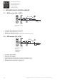
R&M Materials Handling, Inc. 4501 Gateway Boulevard Springfield, Ohio 45502 P.: (937) 328-5100 FAX: (937) 325-5319 2 DESCRIPTION OF CONTROL MODES 2.1 MS2-control (S4-1=OFF) c_coms2a A. Push button position B. Speed S1 means “drive minimum speed forward” S2 means “drive minimum speed reverse” SP2 means “maximum speed” When S1 and S2 or are not active the inverter decelerates to zero 2.2 EP2-control (S4-1=ON) c_coep2a A. Push button position B. Speed 0. Decelerate 1. Maintain speed 2.
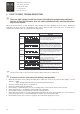
R&M Materials Handling, Inc. 4501 Gateway Boulevard Springfield, Ohio 45502 P.: (937) 328-5100 FAX: (937) 325-5319 3 FAULT CODES, TROUBLESHOOTING There are high voltages inside the inverter (including the programming switches). Wait for at least three minutes after the supply voltage has been switched off before any service actions. When the inverter detects a fault situation it stops running and starts signalling the fault code by blinking the indication leds (green and red).
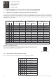
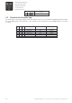
R&M Materials Handling, Inc. 4501 Gateway Boulevard Springfield, Ohio 45502 P.: (937) 328-5100 FAX: (937) 325-5319 4 PROGRAMMING OF THE APPLICATION PARAMETERS 4.1 Minimum speed, maximum speed and ramp time The adjustment ranges of maximum and minimum speed depend on the selected motor type (i.e. motor nominal frequency). The speeds in the speed table A are used for the 100/120Hz motors and the speeds in the speed table B for the 80Hz motors and in the speed table D for the 35Hz motors.
R&M Materials Handling, Inc. 4501 Gateway Boulevard Springfield, Ohio 45502 P.: (937) 328-5100 FAX: (937) 325-5319 Switch S3 -1 -2 -3 0 1 0 4.2 -4 1 Acceleration/deceleration ramp time 8.0 sec Selection of the motor type The motor type is selected by switches S4-2, S4-3 and S4-4. There are several motor dependant parameters which are set according to the selected motor (i.e. the operator selects a parameter set).