INSTALLATION & MAINTENANCE MANUAL EZ LIFT MANUAL PRODUCTS English STD-R-KHA-F-CQD-ENG This document and the information contained herein, is the exclusive property of R&M Materials Handling, Inc. and represents a non-public, confidential and proprietary trade secret that may not be reproduced, disclosed to third parties, altered or otherwise employed in any manner whatsoever without the express written consent of R&M Materials Handling, Inc. Copyright © (2011) R&M Materials Handling, Inc.
EZ Lift Manual Products I&M Manual/EN/02.11.11 m m CAUTION: Read the instructions supplied with the product before installation and commissioning. CAUTION: Keep the instructions in a safe place for future reference. CONTACT INFORMATION R&M MATERIALS HANDLING, INC. 4501 Gateway Boulevard Springfield, OH 45502 General Telephone: 937 - 328-5100 Toll Free Telephone (US): 800 - 955-9967 General Fax: 937 - 325-5319 Parts Department Fax (US): 800 - 955-5162 Parts Dept.
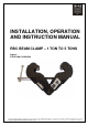
INSTALLATION, OPERATION AND INSTRUCTION MANUAL RBC BEAM CLAMP – 1 TON TO 5 TONS English STD-R-KHA-F-CQD-ENG This document and the information contained herein, is the exclusive property of R&M Materials Handling, Inc., and represents a non-public, confidential and proprietary trade secret that may not be reproduced, disclosed to third parties, altered or otherwise employed in any manner whatsoever without the express written consent of R&M Materials Handling, Inc.
RBC BEAM CLAMP I&M MANUAL/EN/06.17.09 m m CAUTION: Read the instructions supplied with the product before installation and commissioning. CAUTION: Keep the instructions in a safe place for future reference. Table of contents 1 2 INSTRUCTIONS TO READ BEFORE USE ............................................................................................... 3 TECHNICAL CHARACTERISTICS ...........................................................................................................
RBC BEAM CLAMP I&M MANUAL/EN/06.17.09 1 INSTRUCTIONS TO READ BEFORE USE m CAUTION Never modify the beam clamp unless the manufacturer has studied and authorized the modification. Never modify the values and adjustments of the safety components, outside the limits provided for in the manual, or without the approval of the manufacturer. Never try to repair such as welding on the beam clamp without the authorization of the manufacturer or a trained maintenance agent.
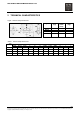
RBC BEAM CLAMP I&M MANUAL/EN/06.17.09 2 TECHNICAL CHARACTERISTICS Figure 1. Beam Clamp Dimensions Type SWL (kg) RBC RBC RBC RBC 1000 2000 3000 5000 1 2 3 5 Beam width (mm) 75-230 75-230 80-320 90-310 Weight (kg) 3.9 5 9.5 11.3 Table 1.
INSTALLATION, OPERATION AND INSTRUCTION MANUAL RM SERIES II MANUAL CHAIN HOIST English STD-R-KHA-F-CQD-ENG This document and the information contained herein, is the exclusive property of R&M Materials Handling, Inc., and represents a non-public, confidential and proprietary trade secret that may not be reproduced, disclosed to third parties, altered or otherwise employed in any manner whatsoever without the express written consent of R&M Materials Handling, Inc.
RM SERIES II I&M MANUAL/EN/02.11.11 m m CAUTION: Read the instructions supplied with the product before installation and commissioning. CAUTION: Keep the instructions in a safe place for future reference. Before proceeding with the operation or maintenance of the equipment it is important that the operating and maintenance personnel read this bulletin carefully in order to ensure the safe and efficient use of the equipment.
RM SERIES II I&M MANUAL/EN/02.11.11 Foreword This manual has been prepared to acquaint you of the procedures necessary for the installation, operation and maintenance of the equipment you have purchased. Proper use is important to the ultimate performance of this equipment. Careful study of and adherence to the instructions will help ensure safe, dependable operation. It is also recommended that you keep this manual readily accessible to operators as well as maintenance and safety personnel.
RM SERIES II I&M MANUAL/EN/02.11.11 m m CAUTION: Read the instructions supplied with the product before installation and commissioning. CAUTION: Keep the instructions in a safe place for future reference. Table of contents 1 2 3 4 5 6 GENERAL .................................................................................................................................................. 5 1.1 Description ...............................................................................................
RM SERIES II I&M MANUAL/EN/02.11.11 1 GENERAL Check that the equipment furnished corresponds with the details on the packing slip attached to the packaging. Limit loads to half of the nominal load capacity during periods of extreme cold weather where the ambient temperature is less than 5°F [-15 °C]. 1.1 Description Figure 1.
RM SERIES II I&M MANUAL/EN/02.11.11 1.2 Installation 1.2.1 Support • • Make sure the supporting structure is designed to withstand the loads and forces imposed by the hoist/trolley. Make sure trolley stops are installed at the limits of trolley travel. Trolley stops shall not be used as a continuing means of stopping the trolley, if a trolley is used. 1.2.2 Start-up Check Points Before operating the new unit, carry out the following start-up procedures: • • • • • • • • 1.
RM SERIES II I&M MANUAL/EN/02.11.11 1.4 Operating Practices In addition to the Safe Operating Practices – Dos and Don’ts, it is recommended that the following operating practices be adhered to when using a manual chain hoist. The operator shall familiarize himself with the operation of the equipment and its proper care. If adjustments are necessary or damage is known, the unit must be removed from service and not used until corrections are made.
RM SERIES II I&M MANUAL/EN/02.11.11 3 SAFE OPERATING PRACTICES – DO’S AND DON'TS 3.1 DO’S: 3.1.1 General Read the manual carefully and always follow the recommendations, instructions, warning information, and make all people who will operate the equipment aware of these. Only use "original parts" when repairing or maintaining. Keep the manual near the equipment and readily available to the operator and the maintenance and safety personnel at all times. 3.1.
RM SERIES II I&M MANUAL/EN/02.11.11 3.2 DON’TS: 3.2.1 Transport / Storage Do not put the equipment on anything without suitable support otherwise parts on the underside may become damaged. 3.2.2 Installation / Maintenance / Servicing • • • Never modify the equipment without the authorization of the manufacturer. Never modify the values and adjustments of the safety devices beyond the ranges specified in the instruction manual or without the manufacturer’s approval.
RM SERIES II I&M MANUAL/EN/02.11.11 4 INSPECTION 4.1 Load Chain Check the condition of the load chain regularly. Never use the equipment if any of its links are cracked or deformed. Link wear must not exceed 10 % of the specified diameter of the load chain. Measure the load chain over 5 links + 2 diameters as shown below in the Load Chain Technical Specification section. Compare the measurement with the appropriate value of the Dimension over 5 links + 2 diameters for a new load chain.
RM SERIES II I&M MANUAL/EN/02.11.11 4.3 Load Chain Installation 1. Take a flexible wire of about 20 inches (50 cm) in length and insert the wire between the load wheel and the chain guide until it comes out on the other side. 2. Hook the chain onto the end of the wire on the load side. 3. Pull the wire to bring the chain in contact with the load wheel while checking the position of the vertical links. The link weld must be on the inside. (See figure) 4. Regulate the load chain tension. 5.
RM SERIES II I&M MANUAL/EN/02.11.11 4.4 Hook Inspection Check the hooks for deformation or cracks. The hooks must be replaced if the throat opening has increased by more than 15%, or if the throat opening has more than 10-degree twist from the plane of the unbent hook. Figure 3.
RM SERIES II I&M MANUAL/EN/02.11.11 4.5 Hook Certificate Table 2. Hook Dimensions Hook I.D. Load Test load Breaking load D O B Hh Lh Hv Lv inch mm 1.22 31 1.24 31.5 1.476 37.5 1.673 42.5 1.772 45 1.969 50 2.087 53 2.953 75 2.953 75 inch mm 0.9449 24 0.9843 25 1.181 30 1.319 33.5 1.398 35.5 1.575 40 1.673 42.5 2.362 60 2.362 60 inch mm 0.6299 16 0.7874 20 0.9291 23.6 1.043 26.5 1.102 28 1.24 31.5 1.319 33.5 1.870 47.5 1.870 47.5 inch mm 0.7008 17.8 1.012 25.7 1.319 33.5 1.575 40 1.72 43.7 2.
RM SERIES II I&M MANUAL/EN/02.11.11 5 PREVENTATIVE MAINTENANCE 5.1 Maintenance Schedule The maintenance and inspection intervals are based on normal duty under normal environmental conditions (free from excessive dust, moisture, and corrosive fumes). If duty is heavier or environment more severe, maintenance and inspection intervals should be shortened and more frequent. Table 3.
RM SERIES II I&M MANUAL/EN/02.11.11 5.2.3 Replacement Criteria for Brakes Table 4. Replacement Criteria for Brakes TON - ITEM THICKNESS AS NEW REPLACE WHEN 1/4 1/2 11 1/2 2- 52308624 52308625 52308626 52308627 52308712 0.125 inches 0.102 inches 0.098 inches 0.100 inches 0.102 inches (3.18 mm) (2.59 mm) (2.50 mm) (2.55 mm) (2.59 mm) 0.086 inches 0.063 inches 0.059 inches 0.061 inches 0.063 inches (2.18 mm) (1.59 mm) (1.50 mm) (1.55 mm) (1.
RM SERIES II I&M MANUAL/EN/02.11.11 5.3 Setting the Overload Limiting Device Figure 6. Cross Section of Overload Limiting Device 1. 2. 3. 4. 5. Hand chain wheel Brake disc Connection plate Screw M5 x 15 (3) Disc spring set Stackup springs of Friction surfaces the disc Setting the overload device 1. 2. 3. 4. 5. Make sure the friction surfaces are clean, free from any rust, dirt, dust, etc. Lightly lubricate the friction surfaces with grease. Tighten each M5 screw (4) evenly until tight.
RM SERIES II I&M MANUAL/EN/02.11.11 6 SPARE PARTS Figure 7. Spare Parts Diagrams 17/20 This document and the information contained herein, is the exclusive property of R&M Materials Handling, Inc., and represents a non-public, confidential and proprietary trade secret that may not be reproduced, disclosed to third parties, altered or otherwise employed in any manner whatsoever without the express written consent of R&M Materials Handling, Inc. Copyright © (2011) R&M Materials Handling, Inc.
RM SERIES II I&M MANUAL/EN/02.11.11 Table 5.
RM SERIES II I&M MANUAL/EN/02.11.
RM SERIES II I&M MANUAL/EN/02.11.
OPERATION AND MAINTENANCE MANUAL 1/4 TON TO 3 TON CAPACITY RL MANUAL LEVER PULLER English STD-R-KHA-F-CQD-ENG This document and the information contained herein, is the exclusive property of R&M Materials Handling, Inc., and represents a non-public, confidential and proprietary trade secret that may not be reproduced, disclosed to third parties, altered or otherwise employed in any manner whatsoever without the express written consent of R&M Materials Handling, Inc.
RL I&M MANUAL/EN/06.17.09 m m CAUTION: Read the instructions supplied with the product before installation and commissioning. CAUTION: Keep the instructions in a safe place for future reference. Before proceeding with the operation or maintenance of the equipment it is important that the operating, and maintenance personnel read this bulletin carefully in order to ensure the safe and efficient use of the equipment.
RL I&M MANUAL/EN/06.17.09 FOREWORD This manual has been prepared to acquaint you of the procedures necessary for the installation, operation and maintenance of the equipment you have purchased. Proper use is important to the ultimate performance of this equipment. Careful study of and adherence to the instructions will help ensure safe, dependable operation. It is also recommended that you keep this manual readily accessible to operators as well as maintenance and safety personnel.
RL I&M MANUAL/EN/06.17.09 Table of contents 1 2 3 4 5 6 GENERAL .................................................................................................................................................. 5 1.1 Description ............................................................................................................................................ 5 1.2 Start-up .........................................................................................................................
RL I&M MANUAL/EN/06.17.09 1 GENERAL Check that the equipment furnished corresponds with the details on the packing slip attached to the packaging. Limit loads to half of the nominal load capacity during periods of extreme cold weather where the ambient temperature is less than 5°F [-15 °C]. 1.1 Description Figure 1. Main Hoist Components Operating Control Lever Serial number and capacity label Lever Handle Load Hook 1.
RL I&M MANUAL/EN/06.17.09 1.3 Operating Procedures The control functions (UP-NEUTRAL-DOWN) are clearly identified on the unit. The unit has a free-chaining (wheeling) capability, which allows the operator to adjust the load hook position when the unit is not under load. Free-chaining capability is activated when the operating control lever is in the neutral position. 1.
RL I&M MANUAL/EN/06.17.09 3 SAFE OPERATING PRACTICES – DO’S AND DON'TS 3.1 DO’S: 3.1.1 General Read the manual carefully and always follow the recommendations, instructions, warning information, and make all people who will operate the equipment aware of these. Only use "original parts" when repairing or maintaining. Keep the manual near the equipment and readily available to the operator and the maintenance and safety personnel at all times. 3.1.
RL I&M MANUAL/EN/06.17.09 3.2 DON’TS: 3.2.1 Transport / Storage Do not put the equipment on anything without suitable support otherwise parts on the underside may become damaged. 3.2.2 Installation / Maintenance / Servicing • • • Never modify the equipment without the authorization of the manufacturer. Never modify the values and adjustments of the safety devices beyond the ranges specified in the instruction manual or without the manufacturer’s approval. Never override limiting or safety equipment.
RL I&M MANUAL/EN/06.17.09 4 INSPECTIONS 4.1 Load Chain Inspection Check the condition of the load chain regularly. Never use the equipment if any of its links are cracked or deformed. Link wear must not exceed 10 % of the specified diameter of the load chain. Measure the load chain over 5 links + 2 diameters as shown below in the Load Chain Technical Specification section. Compare the measurement with the appropriate value of the Dimension over 5 links + 2 diameters for a new load chain.
RL I&M MANUAL/EN/06.17.09 4.1.2 Load Chain Installation 1. Release the control lever. 2. Take a flexible wire of about 20 inches (50 cm) in length and insert it over the lifting head axle until it comes out on the other side. 3. Hook the chain onto the end of the wire on the load side. 4. Pull the wire to bring the chain in contact with the load wheel while checking the position of the vertical links. The link weld must be on the inside. (See figure) 5. Regulate the chain tension. 6.
RL I&M MANUAL/EN/06.17.09 4.2 Hook Inspection Check the hooks for deformation or cracks. The hooks must be replaced if the throat opening has increased by more than 15%, or if the throat opening has more than 10-degree twist from the plane of the unbent hook. Figure 3.
RL I&M MANUAL/EN/06.17.09 4.3 Hook Certificate Table 2. Hook Dimensions Hook Load I.D. capacity Ton 13S 19S 21S 24S Load test kg lbs [kg] 1102 ¼ 250 [500] 4409 3/4 750 [2000] 6614 1 1/2 1500 [3000] 13228 3 3000 [6000] Minimum breaking load lbs [kg] 2204 [1000] 8818 [4000] 13228 [6000] 26456 [12000] D O B Hh Lh Hv Lv in [mm] 1.043 [26.5] 1.476 [37.5] 1.673 [42.5] 1.968 [50] in [mm] 0.835 [21.2] 1.181 [30] 1.319 [33.5] 1.575 [40] in [mm] 0.669 [17] 0.929 [23.6] 1.043 [26.5] 1.240 [31.
RL I&M MANUAL/EN/06.17.09 5 PREVENTATIVE MAINTENANCE 5.1 Maintenance Schedule The maintenance and inspection intervals are based on normal duty under normal environmental conditions (free from excessive dust, moisture, and corrosive fumes). If duty is heavier or environment more severe, maintenance and inspection intervals should be shortened and more frequent. Table 3.
RL I&M MANUAL/EN/06.17.09 6 6.1 SPARE PARTS ¼ ton [250 kg] capacity unit Figure 5. Spare Parts Diagram 14/18 This document and the information contained herein, is the exclusive property of R&M Materials Handling, Inc., and represents a non-public, confidential and proprietary trade secret that may not be reproduced, disclosed to third parties, altered or otherwise employed in any manner whatsoever without the express written consent of R&M Materials Handling, Inc.
RL I&M MANUAL/EN/06.17.09 Table 4.
RL I&M MANUAL/EN/06.17.09 6.2 3/4 ton [750 kg] and higher capacity units Figure 6. Spare Parts Diagram 16/18 This document and the information contained herein, is the exclusive property of R&M Materials Handling, Inc., and represents a non-public, confidential and proprietary trade secret that may not be reproduced, disclosed to third parties, altered or otherwise employed in any manner whatsoever without the express written consent of R&M Materials Handling, Inc.
RL I&M MANUAL/EN/06.17.09 Table 5.
RL I&M MANUAL/EN/06.17.09 THIS PAGE INTENTIONALLY LEFT BLANK 18/18 This document and the information contained herein, is the exclusive property of R&M Materials Handling, Inc., and represents a non-public, confidential and proprietary trade secret that may not be reproduced, disclosed to third parties, altered or otherwise employed in any manner whatsoever without the express written consent of R&M Materials Handling, Inc. Copyright © (2009) R&M Materials Handling, Inc. All rights reserved.
OPERATION AND MAINTENANCE MANUAL ¾ TON TO 6 TON CAPACITY RLP PREMIUM MANUAL LEVER PULLER 3/4 English STD-R-KHA-F-CQD-ENG This document and the information contained herein, is the exclusive property of R&M MATERIALS HANDLING, INC. and represents a non-public, confidential and proprietary trade secret that may not be reproduced, disclosed to third parties, altered or otherwise employed in any manner whatsoever without the express written consent of R&M MATERIALS HANDLING, INC. .
RLP I&M MANUAL/EN/07.20.10 m m CAUTION: Read the instructions supplied with the product before installation and commissioning. CAUTION: Keep the instructions in a safe place for future reference. Before proceeding with the operation or maintenance of the equipment it is important that the operating, and maintenance personnel read this bulletin carefully in order to ensure the safe and efficient use of the equipment.
RLP I&M MANUAL/EN/07.20.10 FOREWORD This manual has been prepared to acquaint you of the procedures necessary for the installation, operation and maintenance of the equipment you have purchased. Proper use is important to the ultimate performance of this equipment. Careful study of and adherence to the instructions will help ensure safe, dependable operation. It is also recommended that you keep this manual readily accessible to operators as well as maintenance and safety personnel.
RLP I&M MANUAL/EN/07.20.10 Table of contents 1 2 3 4 5 6 GENERAL .................................................................................................................................................. 5 1.1 Description ......................................................................................................................................... 5 1.2 Start-up Check Points ..............................................................................................................
RLP I&M MANUAL/EN/07.20.10 1 GENERAL Check that the equipment furnished corresponds with the details on the packing slip attached to the packaging. Limit loads to half of the nominal load capacity during periods of extreme cold weather where the ambient temperature is less than 5°F [-15 °C]. 1.1 Description Figure 1. Main Hoist Components Operating Control Lever Serial number and capacity Load hook 1.
RLP I&M MANUAL/EN/07.20.10 1.4 Operating Practices In addition to the Safe Operating Practices – Dos and Don’ts, it recommended that the following operating practices (taken in part from American National Standards ASME HST-3M) be adhered to when using a lever-operated puller. • • • • • • • 1.5 • • • • • • • • • 2 The supporting structure or anchoring means shall have a load rating at least equal to that of the hoist.
RLP I&M MANUAL/EN/07.20.10 3 SAFE OPERATING PRACTICES – DO’S AND DON'TS 3.1 DO’S: 3.1.1 General Read the manual carefully and always follow the recommendations, instructions, warning information, and make all people who will operate the equipment aware of these. Only use "original parts" when repairing or maintaining. Keep the manual near the equipment and readily available to the operator and the maintenance and safety personnel at all times. 3.1.
RLP I&M MANUAL/EN/07.20.10 3.2 DON’TS: 3.2.1 Transport / Storage Do not put the equipment on anything without suitable support otherwise parts on the underside may become damaged. 3.2.2 Installation / Maintenance / Servicing • • • Never modify the equipment without the authorization of the manufacturer. Never modify the values and adjustments of the safety devices beyond the ranges specified in the instruction manual or without the manufacturer’s approval. Never override limiting or safety equipment.
RLP I&M MANUAL/EN/07.20.10 4 4.1 INSPECTIONS Load Chain Inspection Check the condition of the load chain regularly. Never use the equipment if any of its links are cracked or deformed. Link wear must not exceed 10 % of the specified diameter of the load chain. Measure the load chain over 5 links + 2 diameters as shown below in the Load Chain Technical Specification section. Compare the measurement with the appropriate value of the Dimension over 5 links + 2 diameters for a new load chain.
RLP I&M MANUAL/EN/07.20.10 4.1.2 Load Chain Installation 1. Release the control lever. 2. Take a flexible wire of about 20 inches (50 cm) in length and insert it over the lifting head axle until it comes out on the other side. 3. Hook the chain onto the end of the wire on the load side. 4. Pull the wire to bring the chain in contact with the load wheel while checking the position of the vertical links. The link weld must be on the inside. (See figure) 5. Regulate the chain tension. 6.
RLP I&M MANUAL/EN/07.20.10 4.2 Hook Inspection Check the hooks for deformation or cracks. The hooks must be replaced if the throat opening has increased by more than 15%, or if the throat opening has more than 10-degree twist from the plane of the unbent hook. Figure 3.
RLP I&M MANUAL/EN/07.20.10 4.3 Hook Certificate Table 2. Hook Dimensions Load Capacity Load Test Minimum Breaking Load lbs [kg] lbs [kg] 3307 [1500] 6614 1 1/2 1500 [3000] 13228 3 3000 [6000] 26456 6 6000 [12000] 6614 [3000] 13228 [6000] 26456 [12000] 52912 [24000] Ton 3/4 kg 750 D in [mm] 1.378 [35] 1.575 [40] 2.047 [52] 2.362 [60] O B Hh Lh Hv Lv in [mm] in [mm] in [mm] in [mm] in [mm] in [mm] 0.906 [23] 1.141 [29] 1.516 [38.5] 1.811 [46] 0.709 [18] 0.906 [23] 1.102 [28] 1.
RLP I&M MANUAL/EN/07.20.10 4.4 Replacement Criteria for Brakes Table 3. Replacement Criteria for Brakes TON - ITEM - THICKNESS AS NEW REPLACE WHEN 3/4 1 1/2 - 52308974 52308975 0.166 inches (4.21 mm) 0.146 inches (3.71 mm) 0.126 inches (3.21 mm) 0.107 inches (2.71 mm) 36- 52308976 52308977 0.144 inches (3.66 mm) 0.144 inches (3.66 mm) 0.105 inches (2.66 mm) 0.105 inches (2.66 mm) Figure 5.
RLP I&M MANUAL/EN/07.20.10 5 PREVENTATIVE MAINTENANCE 5.1 Maintenance Schedule The maintenance and inspection intervals are based on normal duty under normal environmental conditions (free from excessive dust, moisture, and corrosive fumes). If duty is heavier or environment more severe, maintenance and inspection intervals should be shortened and more frequent. Table 4.
RLP I&M MANUAL/EN/07.20.10 6 SPARE PARTS Figure 6. Spare Parts Diagrams 15/18 This document and the information contained herein, is the exclusive property of R&M MATERIALS HANDLING, INC. and represents a non-public, confidential and proprietary trade secret that may not be reproduced, disclosed to third parties, altered or otherwise employed in any manner whatsoever without the express written consent of R&M MATERIALS HANDLING, INC. . Copyright © (2010) R&M MATERIALS HANDLING, INC. All rights reserved.
RLP I&M MANUAL/EN/07.20.10 Table 5.
RLP I&M MANUAL/EN/07.20.10 Item 18 19 20 21 22 23 24 25 26 27 28 29 30 31 32 33 34 35 35 35 35 36 37 37 37 37 37 38 39 40 41 42 43 44 45 46 47 47 47 47 47 Description Ratchet Brake cover Spring Locking nut Handle cover assembly Changeover gear Changeover pawl Changeover spring Pawl Spring Handle sleeve Lever handle assembly Hex head screw Hand wheel Spring washer Screw Castle nut Split pin 5.6 x 17 Grade 100 load chain 7.
RLP I&M MANUAL/EN/07.20.10 THIS PAGE INTENTIONALLY LEFT BLANK 18/18 This document and the information contained herein, is the exclusive property of R&M MATERIALS HANDLING, INC. and represents a non-public, confidential and proprietary trade secret that may not be reproduced, disclosed to third parties, altered or otherwise employed in any manner whatsoever without the express written consent of R&M MATERIALS HANDLING, INC. . Copyright © (2010) R&M MATERIALS HANDLING, INC. All rights reserved.
INSTRUCTION MANUAL RPT PUSH TROLLEY / RPTC HAND-GEARED TROLLEY RPT / RPTC English STD-R-KHA-F-CQD-ENG This document and the information contained herein, is the exclusive property of R&M Materials Handling, Inc., and represents a non-public, confidential and proprietary trade secret that may not be reproduced, disclosed to third parties, altered or otherwise employed in any manner whatsoever without the express written consent of R&M Materials Handling, Inc. Copyright © (2009) R&M Materials Handling, Inc.
RPT / RPTC INSTRUCTION MANUAL/EN/06.17.09 FOREWORD This manual has been prepared to acquaint you of the procedures necessary for the installation, operation, and maintenance of the equipment you have purchased. Proper installation is important to the ultimate performance of this equipment. Careful study of and adherence to the instructions will help ensure safe, dependable operation.
RPT / RPTC INSTRUCTION MANUAL/EN/06.17.09 m m CAUTION: Read the instructions supplied with the product before installation and commissioning. CAUTION: Keep the instructions in a safe place for future reference. Table of contents 1 2 3 4 5 6 INSTALLATION ......................................................................................................................................... 4 1.1 Trolley Adjustment ........................................................................................
RPT / RPTC INSTRUCTION MANUAL/EN/06.17.09 1 INSTALLATION Check that: The beam is adequate for the loads to be supported. The beam flange dimensions correspond to the trolley to be installed. The wheels will be able to travel freely along the rail. All nuts are properly tightened and include the cotter pin. The trolley wheels have adequate clearance along the entire length of rail. The end stops are in place before operating. 1.
RPT / RPTC INSTRUCTION MANUAL/EN/06.17.09 Trolley assembly procedure 1. Place the equal number of spacers of the same length on the cross shaft in between the side plates to achieve approximately 1/8” [3 mm] of total wheel clearance between the rail and wheel flanges. 2. Place and distribute equally the spare spacers on the exterior side of both side plates. 3. Hand-tighten the nuts to hold the trolley side plates together. 4.
RPT / RPTC INSTRUCTION MANUAL/EN/06.17.09 3 RPT PUSH TROLLEY & RPTC HAND-GEARED TROLLEY 3.1 Description of the RPT Push Trolley and the RPTC Hand-geared Trolley The cross shaft of the RPT push trolley and the RPTC hand-geared trolley is suited for the top hook of manual chain hoists or manual lever pullers. In addition, the LM1, LM5 or LM10 electric chain hoists can be adapted to the RPT push trolley, either with a top hook or a lug.
RPT / RPTC INSTRUCTION MANUAL/EN/06.17.09 5 DO’S AND DON'TS 5.1 DO’S: 5.1.1 General Read the manual carefully and always follow its recommendations. Only use "original parts" when repairing or maintenance. Keep this instruction manual near the equipment and readily available to the operator and the maintenance mechanic at all times. 5.1.2 Handling / Storage • • • Handle the equipment by its structure either using the fittings provided for this purpose or in its original packaging.
RPT / RPTC INSTRUCTION MANUAL/EN/06.17.09 5.2 DON’TS: 5.2.1 Handling / Storage Do not put the equipment on anything without suitable support otherwise parts on the underside may become damaged. 5.2.2 Installation / Maintenance / Servicing • • Never modify the equipment. Never overload the equipment. 5.2.3 During Use Never attempt to move a load greater than the capacity indicated on the equipment.
RPT / RPTC INSTRUCTION MANUAL/EN/06.17.09 6 PART NUMBERS Part numbers listed are for complete trolleys. 6.1 RPT Push Trolley Table 5. RPT Push Trolley Part Numbers Model RPT-250 RPT-500 Maximum Capacity lbs. [kg] 550 [250] 1100 [500] RPT-1000 2200 [1000] RPT-2000 4400 [2000] RPT-3000 6600 [3000] RPT-5000 11000 [5000] 6.2 Beam Flange Width Range in [mm] 2 – 7.88 [50 – 200] 2 –7.88 [50 – 200] 7.40 – 12.20 [188 – 310] 2.56 – 7.88 [65 – 200] 7.88 – 12.20 [200 – 310] 3.46 – 7.88 [88 – 200] 7.
RPT / RPTC INSTRUCTION MANUAL/EN/06.17.09 THIS PAGE INTENTIONALLY LEFT BLANK 10/10 This document and the information contained herein, is the exclusive property of R&M Materials Handling, Inc., and represents a non-public, confidential and proprietary trade secret that may not be reproduced, disclosed to third parties, altered or otherwise employed in any manner whatsoever without the express written consent of R&M Materials Handling, Inc. Copyright © (2009) R&M Materials Handling, Inc.
INSTRUCTION MANUAL LOW HEADROOM RMLH PUSH TROLLEY / RMLHC HAND-GEARED TROLLEY RMLH / RMLHC English STD-R-KHA-F-CQD-ENG This document and the information contained herein, is the exclusive property of R&M Materials Handling, Inc., and represents a non-public, confidential and proprietary trade secret that may not be reproduced, disclosed to third parties, altered or otherwise employed in any manner whatsoever without the express written consent of R&M Materials Handling, Inc.
RMLH / RMLHC INSTRUCTION MANUAL/EN/07.20.10 FOREWORD This manual has been prepared to acquaint you of the procedures necessary for the installation, operation, and maintenance of the equipment you have purchased. Proper installation is important to the ultimate performance of this equipment. Careful study of and adherence to the instructions will help ensure safe, dependable operation.
RMLH / RMLHC INSTRUCTION MANUAL/EN/07.20.10 m m CAUTION: Read the instructions supplied with the product before installation and commissioning. CAUTION: Keep the instructions in a safe place for future reference. Table of contents 1 2 3 4 5 6 INSTALLATION ......................................................................................................................................... 4 1.1 Trolley Adjustment ......................................................................................
RMLH / RMLHC INSTRUCTION MANUAL/EN/07.20.10 1 INSTALLATION Check that: The beam is adequate for the loads to be supported. The beam flange dimensions correspond to the trolley to be installed. The wheels will be able to travel freely along the rail. All nuts are properly tightened and include the cotter pin. The trolley wheels have adequate clearance along the entire length of rail. The end stops are in place before operating. 1.
RMLH / RMLHC INSTRUCTION MANUAL/EN/07.20.10 Trolley assembly procedure 1. Place the equal number of spacers of the same length on the cross shaft in between the side plates to achieve approximately 1/8” [3 mm] of total wheel clearance between the rail and wheel flanges. 2. Place and distribute equally the spare spacers on the exterior side of both side plates. 3. Hand-tighten the nuts to hold the trolley side plates together. 4.
RMLH / RMLHC INSTRUCTION MANUAL/EN/07.20.10 3 RMLH PUSH TROLLEY & RMLHC HAND-GEARED TROLLEY 3.1 Description of the RMLH Push Trolley and the RMLHC Handgeared Trolley RMLH and RMLHC trolley models have a single beam flange width to cover a wide range of beam flange widths. The trolley wheels are single flange and crown tread type suitable for Wide Flange beams or tapered flange beams. Wheel bearings are permanently lubricated and do not require greasing.
RMLH / RMLHC INSTRUCTION MANUAL/EN/07.20.10 5.1.2 Handling / Storage • • • Handle the equipment by its structure either using the fittings provided for this purpose or in its original packaging. Store the equipment in a non-aggressive environment away from sources of dust or dampness etc. Regularly clean and protect from corrosion (oiling etc.). 5.1.3 Installation / Maintenance / Servicing • • • • • • • • • • • • Have the equipment installed by mechanically competent and trained personnel.
RMLH / RMLHC INSTRUCTION MANUAL/EN/07.20.10 5.2 DON’TS: 5.2.1 Handling / Storage Do not put the equipment on anything without suitable support otherwise parts on the underside may become damaged. 5.2.2 Installation / Maintenance / Servicing • • Never modify the equipment. Never overload the equipment. 5.2.3 During Use Never attempt to move a load greater than the capacity indicated on the equipment.
RMLH / RMLHC INSTRUCTION MANUAL/EN/07.20.10 6 PART NUMBERS Part numbers listed are for complete trolleys. 6.1 RMLH Push Trolley Table 5. RMLH Push Trolley Part Numbers Model RMLH-500 Maximum Capacity lbs. [kg] 1100 [500] RMLH-1000 2200 [1000] 2.52 – 12.0 [64 – 305] 52426367 RMLH-2000 4400 [2000] 3.46 – 7.88 [88 – 200] 52426368 RMLH-5000 11000 [5000] 4.5 – 7.95 [114 – 202] 52426369 6.2 Beam Flange Width Range in [mm] 1.96 –8.