
User Manual


LM05 SERIES II I&M MANUAL/EN/11.30.2010
48/89
This document and the information contained herein, is the exclusive property of R&M Materials Handling, Inc., and represents a non-public, confidential and proprietary trade secret that
may not be reproduced, disclosed to third parties, altered or otherwise employed in any manner whatsoever without the express written consent of R&M Materials Handling, Inc.
Copyright © (2010) R&M Materials Handling, Inc. All rights reserved.
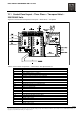
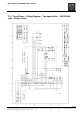
7.14 Control Panel Layout – Three Phase – Two-speed Hoist – 575
volts
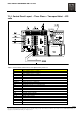
Table 7. Control Panel (Three-Phase Two-Speed 575v) Parts List
ITEM DESCRIPTION
L1 HOIST POWER SUPPLY – PHASE 1
L2 HOIST POWER SUPPLY – PHASE 2
L3 HOIST POWER SUPPLY – PHASE 3
PE POWER SUPPLY GROUND
X1 TERMINAL STRIP ON PRINTED CIRCUIT BOARD
X6 TERMINAL STRIP ON CONTROL TRANSFORMER – NOTE JUMPER CONNECTIONS
BRAKE (-) BRAKE COIL SUPPLY (NEGATIVE)
BRAKE (+)
BRAKE COIL SUPPLY (POSITIVE)
X23 PUSH BUTTON PLUG CONNECTION
X24 MOTORIZED TROLLEY PLUG CONNECTION
K10 MAIN LINE CONTACTOR
K21 HOIST “UP” CONTACTOR
K22 HOIST “DOWN” CONTACTOR
K25 HOIST TWO-SPEED FAST CONTACTOR
T100 CONTROL TRANS FORMER
F100 FUSE HOLDER POSITION
1U, 2U MOTOR SUPPLY LEADS
1V MOTOR SUPPLY LEAD
2V MOTOR SUPPLY LEAD
1W MOTOR SUPPLY LEAD
2W MOTOR SUPPLY LEAD