
Manual

LoadMate
®
LM05
STEPLESS I&M/EN/11.
30
.2010
40/71
This document and the information contained herein, is the exclusive property of R&M Materials Handling, Inc., and represents a non-public, confidential and proprietary trade secret that
may not be reproduced, disclosed to third parties, altered or otherwise employed in any manner whatsoever without the express written consent of R&M Materials Handling, Inc.
Copyright © (2010) R&M Materials Handling, Inc. All rights reserved.
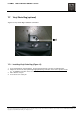
7.10 Control Changes and Fuses
The control panel components are assembled onto a Printed Circuit (PC) Board. The layouts and wiring
diagrams found within this section are for standard hoist controls. The hoist motor brake rectifier is an
integral part of the Printed Circuit (PC) Board.
Stepless hoists are available for the 460 volt three-phase power supplies. The stepless hoist can only be
connected to the specified serial plate voltage.
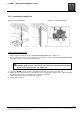
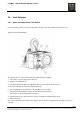
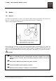
7.10.1 Control Circuit Fuses
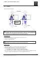
The control fuse for three-phase control panels is located in a vertical, cylindrical fuse holder mounted to the
printed circuit board. The fuse holder is identified as position F100. See Figure 20 for a typical panel view.
The top rotates loose for replacement. There is only one top; therefore, the fuse is located in the position
with the top.
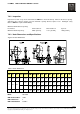
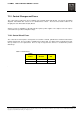
Table 4. Control Fuses
POWER
CONTROL FUSE
SUPPLY VOLTAGE SIZE
3 – PHASE 115 VAC 500 mA
3 – PHASE 48 VAC 630 mA
.