INSTALLATION AND MAINTENANCE MANUAL LM STEPLESS CHAIN HOIST LOADMATE® LM05 STEPLESS CHAIN HOIST English STD-R-KHA-F-CQD-ENG This document and the information contained herein, is the exclusive property of R&M Materials Handling, Inc., and represents a non-public, confidential and proprietary trade secret that may not be reproduced, disclosed to third parties, altered or otherwise employed in any manner whatsoever without the express written consent of R&M Materials Handling, Inc.
® LoadMate LM05 STEPLESS I&M/EN/11.30.2010 THIS PAGE INTENTIONALLY LEFT BLANK 2/71 This document and the information contained herein, is the exclusive property of R&M Materials Handling, Inc., and represents a non-public, confidential and proprietary trade secret that may not be reproduced, disclosed to third parties, altered or otherwise employed in any manner whatsoever without the express written consent of R&M Materials Handling, Inc. Copyright © (2010) R&M Materials Handling, Inc.
® LoadMate LM05 STEPLESS I&M/EN/11.30.2010 m m CAUTION: Read the instructions supplied with the product before installation and commissioning. CAUTION: Keep the instructions in a safe place for future reference. Table of contents 1 2 3 4 5 6 7 INTRODUCTION ........................................................................................................................................5 1.1 Contact Information ..................................................................................
® LoadMate LM05 STEPLESS I&M/EN/11.30.2010 7.5.3 Fall Stop Installation (Figure 13) ............................................................................................... 33 7.6 Chain Container ................................................................................................................................. 34 7.6.1 Removing Chain Container (Figure 14) .................................................................................... 34 7.6.
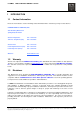
® LoadMate LM05 STEPLESS I&M/EN/11.30.2010 1 1.1 INTRODUCTION Contact Information Please do not hesitate to use the following contact information in the event that you may need assistance: R&M MATERIALS HANDLING, INC. 4501 Gateway Boulevard Springfield, OH 45502 General Telephone: 937 - 328-5100 Toll Free Telephone (US): 800 - 955-9967 General Fax: 937 - 325-5319 Parts Department Fax (US): 800 - 955-5162 Parts Dept. Fax (other): 937 - 328-5162 Website: www.rmhoist.com 1.
® LoadMate LM05 STEPLESS I&M/EN/11.30.2010 1.4 Safety Read and understand this manual before using the hoist. Important issues to remember during installation, operation, maintenance, and inspection are provided at the hoist control stations, at various locations on the hoist, in this manual, and in the LoadMate® Electric Chain Hoist Operator’s Manual.
® LoadMate LM05 STEPLESS I&M/EN/11.30.2010 The words SHALL and SHOULD are used throughout this manual in accordance with definitions in the ASME B30 standards as follows: SHALL indicates a rule is mandatory and must be followed. SHOULD indicates a rule is a recommendation, the advisability of which depends on the facts in each situation.
® LoadMate LM05 STEPLESS I&M/EN/11.30.2010 NOTICE: m It is a responsibility of the owner / user to install, inspect, test, maintain, and operate a hoist in accordance with the ASME B30.16 Safety Standard, OSHA Regulations, and ANSI / NFPA 70, National Electric Code. If the hoist is installed as part of a total lifting system, it is also the responsibility of the owner / user to comply with the applicable ASME B30 volume that addresses other types of equipment used in the system.
® LoadMate LM05 STEPLESS I&M/EN/11.30.2010 2 INSTALLATION m 2.1 DANGER: Before installing, removing, inspection, or performing any maintenance on a hoist, the main switch shall be de-energized. Lock and tag the main switch in the deenergized position in accordance with ANSI Z244.1. Follow other maintenance procedures outlined in this manual and ASME B30.16. General NOTE: Install the breather on the upper part of the hoist.
® LoadMate LM05 STEPLESS I&M/EN/11.30.2010 2.3 Mounting Below are three types of mounting: 1. 2. 3. 4. Hook Mounted Base Mounted Coupling Mounted Trolley Mounted – NOT SHOWN – is accomplished via a Hook or Trolley Coupling to the Trolley Assembly. Figure 1. Mounting Types For all trolley-mounted hoists, refer to appropriate trolley manual for trolley installation instructions. After a trolley-mounted hoist has been assembled to a beam, check for balance.
® LoadMate LM05 STEPLESS I&M/EN/11.30.2010 2.5 Electrical Connection The user / owner must provide the main power supply hardware (cable, conductor bar, fuses, disconnect switch, etc.). m CAUTION: Make sure that the power supply voltage is the same as that shown on hoist serial plate / nameplate. m CAUTION: Make sure that fuses and other current overload devices are in place to protect the power supply.
® LoadMate LM05 STEPLESS I&M/EN/11.30.2010 m m WARNING: Failure to properly ground the hoist presents the danger of electric shock. WARNING: An improper or insufficient ground connection creates an electrical shock hazard when touching any part of the hoist or trolley. 12/71 This document and the information contained herein, is the exclusive property of R&M Materials Handling, Inc.
® LoadMate LM05 STEPLESS I&M/EN/11.30.2010 2.6 Connection Figure 2. Control Box Power Connection NOTE: The electrical configuration can be different according to the specifications of the hoist. See electrical drawing. NOTE: Do not change the travel directions labels in the control box or in the hoist internal wiring. 13/71 This document and the information contained herein, is the exclusive property of R&M Materials Handling, Inc.
® LoadMate LM05 STEPLESS I&M/EN/11.30.2010 3 INITIAL START-UP m WARNING: 3.1 NOTE: Before connecting power to hoist, check all “motion” buttons on pendant control assembly to make sure that they operate freely without binding or sticking. Check pendant cable and strain relief connection to ensure that they are not damaged. General Initial start-up procedures are as follows: Read all attached WARNING tags and placards affixed to hoist.
® LoadMate LM05 STEPLESS I&M/EN/11.30.2010 3.3 Check hoist motor brake function. Run empty load block up or down to check that load block does not drift more than 1.0 inch [25mm]. If so, adjust brake as described in Section 7.3 of this manual. Run empty load block down to check that fall stop (located on free end of load chain) makes proper contact with upper / lower travel safety limit switch and that limit switch functions properly.
® LoadMate LM05 STEPLESS I&M/EN/11.30.2010 4 HOIST OPERATION m WARNING: BEFORE PROCEEDING WITH THE NORMAL OPERATION OF THIS HOIST, THE OPERATOR/(S) SHALL BE TRAINED IN ACCORDANCE WITH THE LoadMate® Electric Chain Hoist Operator’s Manual AS SUPPLIED WITH THIS HOIST.
® LoadMate LM05 STEPLESS I&M/EN/11.30.2010 5 LOW HEADROOM TROLLEY Figure 3. Low headroom trolley 5.1 Description – Technical Characteristics (low headroom trolley) NOTE: The trolley you have just purchased must be used only with the nominal load indicated on the rating plate. NOTE: The trolley’s service life will depend upon the level of duty, the average operating time, the number of starts and the maintenance applied to it. 5.1.
® LoadMate LM05 STEPLESS I&M/EN/11.30.2010 5.1.2 Environmental Data Ambient temperature: -10°C to +40°C Protection degree: IP55 as standard Sound level: 70 decibels at 1 m 5.1.3 Optional equipment Limit Switch: This cuts off the directional movement when the trolley reaches the end of its run. Electric Actuation Device: This actuates the supply line; the slide block must not exceed the rolling profile (A). Brush: This allows for earthing, due to the brush rubbing on the profile element.
® LoadMate LM05 STEPLESS I&M/EN/11.30.2010 6 SWIVEL TROLLEY 6.1 Description – Technical Characteristics (swiveling trolley to 3.2 tons) NOTE: The trolley you have just purchased must be used only with the nominal load indicated on the rating plate. NOTE: The trolley’s service life will depend on the level of duty, the average operating time, the number of starts and the maintenance applied to it. 6.1.
® LoadMate LM05 STEPLESS I&M/EN/11.30.2010 6.2 Installation of Swivel Trolley The service life of the trolley depends upon the way it is installed. The instructions in this manual must be followed carefully for the installation, use and maintenance of the hoist. Any use contrary to these instructions can be dangerous. Do not use hoist until this manual has been fully read and understood. Always keep this manual near the hoist, available to the operator and the person in charge of maintenance.
® LoadMate LM05 STEPLESS I&M/EN/11.30.2010 Figure 4. Drive wheel and idler wheel/side plates Adjust drive wheel and idler wheel/side plates as shown above. 6.3 Electric Swivel Trolley Figure 5. Electric swivel trolley Table 1. Electric swivel trolley HOIST TYPE SWIVELING TROLLEY TYPE CAPACITY NUMBER OF WHEELS WHEEL DIAMETER MOTOR TYPE C05 SWIV32 0 – 1 ton 4 100 2 x TMU 1 (35 Hz) C10 SWIV32 0 – 2 tons 4 100 2 x TMU 2 (100 Hz) C16-20-25 SWIV32 0 – 3.
® LoadMate LM05 STEPLESS I&M/EN/11.30.2010 6.3.1 Swiveling trolley (3.2 tons) Figure 6. Swiveling trolley (3.2 tons) - CAPACITY MAX 3.2 TONS (3200 KG) - RAY OF CURVE MINI 2.6 FEET 6.3.2 Swiveling trolley (3.2 to 5.0 tons) (NOT LOCALLY AVAILABLE) Figure 7. Swiveling trolley (3.2 to 5.0 tons) - CAPACITY MAX 3.2 TO 5 TONS (3200 TO 5000 KG) - RAY OF CURVE MINI 3.9 FEET 22/71 This document and the information contained herein, is the exclusive property of R&M Materials Handling, Inc.
® LoadMate LM05 STEPLESS I&M/EN/11.30.2010 6.3.3 Procedure to adjust swivel trolley guide rollers 1. 2. 3. 4. 5. 6. Loosen nut “A” (8 plcs). Adjust guide rollers the maximum distance away from beam. Place swivel trolley on beam. Move trolley to curve section of beam. Adjust guide rollers allowing approximately 3/16” (4-5 mm) clearance per side using screw “B.” Tighten nut “A” (8 plcs). Figure 8. Swivel trolley guide rollers NOTE: Adjustments should be made with swivel trolley in radius of monorail.
® LoadMate LM05 STEPLESS I&M/EN/11.30.2010 7 MAINTENANCE 7.1 Basic Hoist Construction Figure 9. Basic Hoist Components 1 Main casing 2 Gears 4 Electrical box 5 Brake Flange 3 Brake/slipping clutch/housing assembly NOTE: The hoist which you have just purchased should only be used with a maximum load equal to the nominal load. NOTE: The length of its useful service life depends on the demands placed on it, the average operating time, the number of start-ups and its maintenance.
® LoadMate LM05 STEPLESS I&M/EN/11.30.2010 7.2 Motor / Body The hoist motors are designed to provide dependable hoisting service. The standard motors are enclosed for IP55 rated protection against normal hazards of dust and moisture. The motor bearings are sealed and do not require further greasing. The hoist body is constructed of aluminum and requires no maintenance. Remove from service and replace the hoist body if damaged. 7.
® LoadMate LM05 STEPLESS I&M/EN/11.30.2010 Figure 10. Hoist Brake / Slip Clutch Table 2. Hoist Brake / Slip Clutch Parts List ITEM DESCRIPTION 1 2 3 BRAKE DISC PINS ANCHOR DISC 4 5 6 7 8 9 SPRING BRAKE DISK ANCHOR DISC FLYWHEEL PIN FLYWHEEL CAM SYSTEM 10 11 12 13 14 15 CAM SYSTEM CAM SYSTEM GEAR SHAFT MOTOR SHAFT COVER O-RING 16 17 BRAKE LINING CLUTCH LINING 26/71 This document and the information contained herein, is the exclusive property of R&M Materials Handling, Inc.
® LoadMate LM05 STEPLESS I&M/EN/11.30.2010 m SEE Figure 10 CAUTION: Make sure the motor is not running before placing tool on the nut to adjust it. Do not touch any moving components. m m CAUTION: The slip-clutch generates heat when slipping. ITEMS 3, 8 & 17 absorb this heat. When these items become too hot, clutch adjustment may be difficult due to unstable behavior of friction surfaces. If this happens, allow brake & clutch assembly to cool before trying to re-adjust slip-clutch.
® LoadMate LM05 STEPLESS I&M/EN/11.30.2010 7.4 Load Chain 7.4.1 General m CAUTION: A hoist SHALL NEVER be used if the load chain shows any evidence of mechanical damage or excessive wear. Never use the load chain as a sling. Use only original equipment chain as supplied by a factory authorized source. Improper load chain storage or installation can render the load chain unusable prior to the first lift. 7.4.
® LoadMate LM05 STEPLESS I&M/EN/11.30.2010 Figure 11. Chain Dimensions t 11 t t Ød P25004 Measure the following chain dimensions at several points on chain: (Figure 11) Dimensions of one link ( d x t ) where, d = diameter and t = pitch Length over 11 links ( 11 t ) Replace load chain if any one of these dimensions exceeds maximum allowed wear. Maximum allowed wear: Minimum link diameter allowed (d): 0.1693” [4.30 mm] MINIMUM Maximum pitch allowed (t): 0.5157” [13.10 mm] MAXIMUM (11t): 5.
® LoadMate LM05 STEPLESS I&M/EN/11.30.2010 7.4.3 Load Chain Specifications (see Figure 11) Chain Specification: Load chain Chain type: Standard Diameter (d) x pitch (t): 0.189” (4.8 mm) /0.492” (12.5 mm) Class: DAT Grade: H8S or HIS G80 RAS Maximum working stress: 19,652 lbs/in (135.5 N/mm ) Hardened surface: 580 or 700 HV (Vickers Hardness) Thickness: 0.0039” (0.1 mm) to 0.0079” (0.
® LoadMate LM05 STEPLESS I&M/EN/11.30.2010 7.4.5 Installing the Load Chain Figure 12. Chain Installation Figure 12-A. Chain Orientation 1-FALL CHAIN INSTALLATION 1. Attach last link of chain onto hook of CHAIN INSERTION TOOL (item 1, Figure 12). 2. If the insertion tool is not in the hoist (removal procedure), insert other end of CHAIN INSERTION TOOL into chain opening closest to chain container side.
® LoadMate LM05 STEPLESS I&M/EN/11.30.2010 2-FALL CHAIN INSTALLATION 1. If the chain insertion tool is not in the hoist (removal procedure), attach last link of chain onto hook of CHAIN INSERTION TOOL (item 1, Figure 12). 2. Insert other end of CHAIN INSERTION TOOL into chain opening closest to chain container. m CAUTION: For a 2-Fall load block assembly, make sure the chain weld on chain link faces inward toward chain wheel pocket on hoist and away from idler sprocket of hook block assembly.
® LoadMate LM05 STEPLESS I&M/EN/11.30.2010 7.5 Fall Stop Assembly 7.5.1 General The slack fall stop is a safety stop, not a functional stop. The fall stop must be located at least six (6.0) inches [150mm] from end of last chain link. Figure 13. Installation of Slack Fall Stop 1 2 6'' 3 3 7.5.2 Removing fall stop (Figure 13) 1. 2. 3. 4. Remove cotter pin (item 1). Slide up the tube (item 2). Remove the two fall stop halves (item 3). Slide tube (item 2) off load chain. 7.5.
® LoadMate LM05 STEPLESS I&M/EN/11.30.2010 7.6 Chain Container Figure 14. Chain Container Installation m CAUTION: Chain container must be installed for effective operation of travel limit switch. 7.6.1 Removing Chain Container (Figure 14) 1. Remove cotter pin (item 5) from end of pin (item 3). 2. Pull pin (item 3) out while supporting chain container (item 2). 3. Remove chain container (item 2). 7.6.2 Installing Chain Container (Figure 14) 1. Insert load chain into chain container (item 2).
® LoadMate LM05 STEPLESS I&M/EN/11.30.2010 7.7 Vinyl Chain Bag (optional) Figure 15. Vinyl Chain Bag Installation Connection 7.7.1 Installing Vinyl Chain Bag (Figure 15) 1. Insert load chain into vinyl chain bag. Position vinyl chain bag onto hoist mounting bracket. 2. Align holes and insert cotter pin through appropriate bag connection holes for the specific model. 2.1. Use Item 1 connection holes for the Model 05 hoist. 3. Place washer onto pin. 4. Insert and secure cotter pin.
® LoadMate LM05 STEPLESS I&M/EN/11.30.2010 7.8 Limit Switches 7.8.1 Upper and Lower Gear Limit Switch It is located into the brake cover and is adjusted in our works. This device limits the path of the hook. Figure 16. Gear Limit Switches The setting is done as follows (after load chain replacement for example): 1. Take off the cap of the upper part of the hoist. 2. Remove the guiding bar (1). 3. For upper limit switch: Move the adjustment disc (4) on the bottom side of the hoist. 4.
® LoadMate LM05 STEPLESS I&M/EN/11.30.2010 7.9 Hooks 7.9.1 General Check hooks for deformation or cracks. Hooks must be replaced if throat opening has increased by more than 15%, or if throat opening has more than 10-degree twist from plane of straight hook. Figure 17. Measuring Hook Deformation Due to many types and sizes of hooks that can be furnished and/or specified by the user / owner, it is recommended that user / owner measure the actual throat opening of hook as originally furnished.
® LoadMate LM05 STEPLESS I&M/EN/11.30.2010 7.9.2 Inspection Inspection for wear on top hook and load hook SHALL be checked routinely. Measure the throat opening. (dimension-a2). If throat opening exceeds maximum opening allowed, replace hook. Damaged safety latches SHALL be replaced immediately. Maximum allowed throat opening: Hook Class: 012T load hook 025T load hook top hook Maximum allowed opening: 0.905” [23 mm] 1.181” [30 mm] 1.456”[37mm] 7.9.3 Hook Dimensions and Specifications Figure 18.
® LoadMate LM05 STEPLESS I&M/EN/11.30.2010 7.9.4 Top Hook Figure 19. Top Hook Orientation CHAIN CONTAINER BRACKET m CAUTION: Before removing Top Hook, de-energize the power to the hoist per ANSI Z244.1 and make certain that any load is removed from the load hook. Also support the total weight of the hoist, including chain, prior to removing the Top Hook. Removing Top Hook 1. Place hoist on workbench. Protect limit switches on bottom side of hoist. 2. Remove screw and retaining washer. 3.
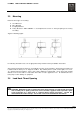
® LoadMate LM05 STEPLESS I&M/EN/11.30.2010 7.10 Control Changes and Fuses The control panel components are assembled onto a Printed Circuit (PC) Board. The layouts and wiring diagrams found within this section are for standard hoist controls. The hoist motor brake rectifier is an integral part of the Printed Circuit (PC) Board. Stepless hoists are available for the 460 volt three-phase power supplies. The stepless hoist can only be connected to the specified serial plate voltage. 7.10.
® LoadMate LM05 STEPLESS I&M/EN/11.30.2010 7.11 Printed Circuit Board (Stepless) Figure 20. Circuit board (Stepless) K10 A1 T100 X22 X23 X24 Table 5.
® LoadMate LM05 STEPLESS I&M/EN/11.30.2010 Table 4.
® LoadMate LM05 STEPLESS I&M/EN/11.30.2010 7.12 Three Phase – Wiring Diagram – Stepless Hoist - 460 volts – Power Circuit 43/71 This document and the information contained herein, is the exclusive property of R&M Materials Handling, Inc., and represents a non-public, confidential and proprietary trade secret that may not be reproduced, disclosed to third parties, altered or otherwise employed in any manner whatsoever without the express written consent of R&M Materials Handling, Inc.
® LoadMate LM05 STEPLESS I&M/EN/11.30.2010 7.13 Three Phase – Wiring Diagram – Stepless Hoist - 460 volts – Control Circuit 44/71 This document and the information contained herein, is the exclusive property of R&M Materials Handling, Inc., and represents a non-public, confidential and proprietary trade secret that may not be reproduced, disclosed to third parties, altered or otherwise employed in any manner whatsoever without the express written consent of R&M Materials Handling, Inc.
® LoadMate LM05 STEPLESS I&M/EN/11.30.2010 7.14 Wiring Diagram – 3 Button – Push Button 45/71 This document and the information contained herein, is the exclusive property of R&M Materials Handling, Inc., and represents a non-public, confidential and proprietary trade secret that may not be reproduced, disclosed to third parties, altered or otherwise employed in any manner whatsoever without the express written consent of R&M Materials Handling, Inc. Copyright © (2010) R&M Materials Handling, Inc.
® LoadMate LM05 STEPLESS I&M/EN/11.30.2010 7.15 Wiring Diagram – 5 Button – Push Button 46/71 This document and the information contained herein, is the exclusive property of R&M Materials Handling, Inc., and represents a non-public, confidential and proprietary trade secret that may not be reproduced, disclosed to third parties, altered or otherwise employed in any manner whatsoever without the express written consent of R&M Materials Handling, Inc. Copyright © (2010) R&M Materials Handling, Inc.
® LoadMate LM05 STEPLESS I&M/EN/11.30.2010 7.16 Wiring Diagram – 7 Button – Push Button 47/71 This document and the information contained herein, is the exclusive property of R&M Materials Handling, Inc., and represents a non-public, confidential and proprietary trade secret that may not be reproduced, disclosed to third parties, altered or otherwise employed in any manner whatsoever without the express written consent of R&M Materials Handling, Inc. Copyright © (2010) R&M Materials Handling, Inc.
® LoadMate LM05 STEPLESS I&M/EN/11.30.2010 8 PREVENTATIVE MAINTENANCE 8.1 Maintenance and Inspection Table Table 6.
® LoadMate LM05 STEPLESS I&M/EN/11.30.2010 8.2 Lubrication Figure 21. Lubrication Specifications Table 7. Lubrication Specifications LUBRICATION POINT SPECIFICATIONS ACCEPTABLE LUBRICANTS QUANTITY Chain Oil or Liquid grease Chain lubricating fluid (Ceplattyn or similar) EP-90 As required Idler sprocket Slide bearing + bearing Grease (without MoS2) KP 2 (DIN 51 502) Soap-based lithium Approx.
® LoadMate LM05 STEPLESS I&M/EN/11.30.2010 8.3 Recommended technical support for various spare parts Table 8.
® LoadMate LM05 STEPLESS I&M/EN/11.30.2010 8.5 Troubleshooting Table 10.
® LoadMate LM05 STEPLESS I&M/EN/11.30.2010 9 9.1 PARTS ILLUSTRATION Hoist Body – Three Phase Power Supply Figure 22. Three Phase Power Supply 52/71 This document and the information contained herein, is the exclusive property of R&M Materials Handling, Inc.
® LoadMate LM05 STEPLESS I&M/EN/11.30.2010 Table 11.
® LoadMate LM05 STEPLESS I&M/EN/11.30.2010 9.2 Mechanism / Brake (Stepless) Figure 23. Mechanism/Brake (Stepless) Table 12.
® LoadMate LM05 STEPLESS I&M/EN/11.30.2010 THIS PAGE INTENTIONALLY LEFT BLANK 55/71 This document and the information contained herein, is the exclusive property of R&M Materials Handling, Inc., and represents a non-public, confidential and proprietary trade secret that may not be reproduced, disclosed to third parties, altered or otherwise employed in any manner whatsoever without the express written consent of R&M Materials Handling, Inc. Copyright © (2010) R&M Materials Handling, Inc.
® LoadMate LM05 STEPLESS I&M/EN/11.30.2010 9.3 Lifting Assembly Figure 24. Lifting Assembly 4 4A 56/71 This document and the information contained herein, is the exclusive property of R&M Materials Handling, Inc., and represents a non-public, confidential and proprietary trade secret that may not be reproduced, disclosed to third parties, altered or otherwise employed in any manner whatsoever without the express written consent of R&M Materials Handling, Inc.
® LoadMate LM05 STEPLESS I&M/EN/11.30.2010 Table 13.
® LoadMate LM05 STEPLESS I&M/EN/11.30.2010 9.4 Controls (Stepless) Figure 25. Controls (Stepless) Table 14.
® LoadMate LM05 STEPLESS I&M/EN/11.30.2010 9.5 Adjust Limit Switch (Stepless) Figure 26. Adjust Limit Switch (Stepless) Table 15. Adjust Limit Switch (Stepless) Parts List ITEM 1 2 PART NUMBER 52337490 8010612 DESCRIPTION SET OF GEAR LIMIT SWITCH 40 m + SHAFT REP. 2 CHC SCREWS M6x12 QTY 1 2 59/71 This document and the information contained herein, is the exclusive property of R&M Materials Handling, Inc.
® LoadMate LM05 STEPLESS I&M/EN/11.30.2010 9.6 Low Headroom Trolley 9.6.1 Low Headroom Trolley (Drive Components) 60/71 This document and the information contained herein, is the exclusive property of R&M Materials Handling, Inc., and represents a non-public, confidential and proprietary trade secret that may not be reproduced, disclosed to third parties, altered or otherwise employed in any manner whatsoever without the express written consent of R&M Materials Handling, Inc.
® LoadMate LM05 STEPLESS I&M/EN/11.30.2010 Table 16.
® LoadMate LM05 STEPLESS I&M/EN/11.30.2010 9.6.2 Low Headroom Trolley (Suspension Components) Figure 27. Low headroom trolley (suspension components) 62/71 This document and the information contained herein, is the exclusive property of R&M Materials Handling, Inc.
® LoadMate LM05 STEPLESS I&M/EN/11.30.2010 Table 17. Low Headroom Trolley (Suspension Components) ITEM C10 SHORT DESCRIPTION QTY CODE 1 LH Short Outreach Frame Assy 1 52391065 2 Fixed point assy (not applicable for 1-fall hoists) 1 52391075 to 65 ft. 1 52333407 66 to130 ft. 1 52328053 3 Chain bag (from 0 to 30 m) 4 Lifting chain galva. (Length: HOL + 5 ft.
® LoadMate LM05 STEPLESS I&M/EN/11.30.2010 9.7 Electric trolley (Swiveling trolley 0 to 3.2 Tons (3200 Kg)) Figure 28. Electric trolley (swiveling trolley 0 to 3.2 tons (3200 Kg)) 5 NOTE: ECH is attached to swivel trolley through a mechanical connection. No top hook connection available. 64/71 This document and the information contained herein, is the exclusive property of R&M Materials Handling, Inc.
® LoadMate LM05 STEPLESS I&M/EN/11.30.2010 Table 18. Electric trolley (Swiveling trolley 0 to 3.2 Tons (3200 Kg)) ITEM DESCRIPTION Complete 2-speed motor drive 115Vc 460V 575V ≤ 3.2 Ton (3200 Kg) 208/230V 1 Complete inverter motor drive 115Vc 460V 575V 208/230V ≤ 1 Ton (1000 Kg) > 1 Ton ≤ 3.2 Ton QTY CODE 2 52306026 2 52306027 2 52306028 2 52299090 2 52304881 2 Idler side plate 2 52326596 3 Drive side plate 2 52326597 Swivel CHRD Kit 2.60 – 4.33 in.
® LoadMate LM05 STEPLESS I&M/EN/11.30.2010 9.8 Push Button Assembly – Horizontal Pairs of Buttons Figure 29. Push Button Assembly – Horizontal Pairs of Buttons Table 19.
® LoadMate LM05 STEPLESS I&M/EN/11.30.2010 9.9 Pushbutton Assembly – Horizontal Pairs of Buttons Figure 30. Pushbutton Assembly – Horizontal Pairs of Buttons 1 3 2 Table 20.
® LoadMate LM05 STEPLESS I&M/EN/11.30.2010 9.10 Push Button Assembly – Vertical Pairs of Buttons (Option) Figure 31. Pushbutton Assembly – Vertical Pairs of Buttons (Option) 68/71 This document and the information contained herein, is the exclusive property of R&M Materials Handling, Inc.
® LoadMate LM05 STEPLESS I&M/EN/11.30.2010 Table 21.
® LoadMate LM05 STEPLESS I&M/EN/11.30.2010 9.11 Push Button Assembly – Vertical Buttons (Option) Figure 32. Push Button Assembly – Vertical Buttons (Option) Table 22.
® LoadMate LM05 STEPLESS I&M/EN/11.30.2010 THIS PAGE INTENTIONALLY LEFT BLANK 71/71 This document and the information contained herein, is the exclusive property of R&M Materials Handling, Inc., and represents a non-public, confidential and proprietary trade secret that may not be reproduced, disclosed to third parties, altered or otherwise employed in any manner whatsoever without the express written consent of R&M Materials Handling, Inc. Copyright © (2010) R&M Materials Handling, Inc.