INSTALLATION AND MAINTENANCE MANUAL LM CHAIN HOIST LOADMATE® LM16 - LM20 – LM25 English STD-R-KHA-F-CQD-ENG This document and the information contained herein, is the exclusive property of R&M Materials Handling, Inc., and represents a non-public, confidential and proprietary trade secret that may not be reproduced, disclosed to third parties, altered or otherwise employed in any manner whatsoever without the express written consent of R&M Materials Handling, Inc.
LM16-20-25 I&M MANUAL/EN/11.30.2010 THIS PAGE INTENTIONALLY LEFT BLANK 2/73 This document and the information contained herein, is the exclusive property of R&M Materials Handling, Inc., and represents a non-public, confidential and proprietary trade secret that may not be reproduced, disclosed to third parties, altered or otherwise employed in any manner whatsoever without the express written consent of R&M Materials Handling, Inc. Copyright © (2010) R&M Materials Handling, Inc. All rights reserved.
LM16-20-25 I&M MANUAL/EN/11.30.2010 m m CAUTION: Read the instructions supplied with the product before installation and commissioning. CAUTION: Keep the instructions in a safe place for future reference. Table of contents 1 2 3 4 5 6 INTRODUCTION ........................................................................................................................................ 5 1.1 Contact Information ............................................................................................
LM16-20-25 I&M MANUAL/EN/11.30.2010 6.18 Two Speed – Three Phase – 208 / 230 / 460 Volt – Power Circuit ............................................... 43 6.19 Two Speed – Three Phase – 208 / 230 / 460 Volt – Control Circuit .............................................. 44 6.20 Two Speed – Three Phase – 575 Volt – Power Circuit .................................................................. 45 6.21 Two Speed – Three Phase – 575 Volt – Control Circuit ....................................................
LM16-20-25 I&M MANUAL/EN/11.30.2010 1 1.1 INTRODUCTION Contact Information Please do not hesitate to use the following contact information in the event that you may need assistance: R&M MATERIALS HANDLING, INC. 4501 Gateway Boulevard Springfield, OH 45502 General Telephone: 937 - 328-5100 Toll Free Telephone (US): 800 - 955-9967 General Fax: 937 - 325-5319 Parts Department Fax (US): 800 - 955-5162 Parts Dept. Fax (other): 937 - 328-5162 Website: www.rmhoist.com 1.
LM16-20-25 I&M MANUAL/EN/11.30.2010 1.4 Safety NOTE: Read and understand this manual before using the hoist. Important issues to remember during installation, operation, maintenance, and inspection are provided at the hoist control stations, at various locations on the hoist, in this manual, and in the LoadMate® Electric Chain Hoist Operator’s Manual.
LM16-20-25 I&M MANUAL/EN/11.30.2010 The words SHALL and SHOULD are used throughout this manual in accordance with definitions in the ASME B30 standards as follows: SHALL indicates a rule is mandatory and must be followed. SHOULD indicates a rule is a recommendation, the advisability of which depends on the facts in each situation. Hoist operation, hoist inspection, and hoist maintenance personnel training programs should be based on requirements in accordance with the latest edition of: ASME B30.
LM16-20-25 I&M MANUAL/EN/11.30.2010 NOTICE: m It is a responsibility of the owner / user to install, inspect, test, maintain, and operate a hoist in accordance with the ASME B30.16 Safety Standard, OSHA Regulations, and ANSI / NFPA 70, National Electric Code. If the hoist is installed as part of a total lifting system, it is also the responsibility of the owner / user to comply with the applicable ASME B30 volume that addresses other types of equipment used in the system.
LM16-20-25 I&M MANUAL/EN/11.30.2010 2 INSTALLATION m 2.1 DANGER: Before installing, removing, inspection, or performing any maintenance on a hoist, the main switch shall be de-energized. Lock and tag the main switch in the deenergized position in accordance with ANSI Z244.1. Follow other maintenance procedures outlined in this manual and ASME B30.16. General Prior to installation, the unit shall be checked thoroughly for damage during shipment or handling at the job site.
LM16-20-25 I&M MANUAL/EN/11.30.2010 2.4 Mounting Below are three types of mounting: 1. 2. 3. 4. Hook Mounted Base Mounted Coupling Mounted Trolley Mounted – NOT SHOWN – is accomplished via a Hook or Trolley Coupling to the Trolley Assembly. Figure 1. Mounting Types For all trolley-mounted hoists, refer to appropriate trolley manual for trolley installation instructions. After a trolley-mounted hoist has been assembled to a beam, check for balance.
LM16-20-25 I&M MANUAL/EN/11.30.2010 2.6 Electrical Connection The user / owner must provide the main power supply hardware (cable, conductor bar, fuses, disconnect switch, etc.). m CAUTION: Make sure that the power supply voltage is the same as that shown on hoist serial plate / nameplate. m CAUTION: Make sure that fuses and other current overload devices are in place to protect the power supply.
LM16-20-25 I&M MANUAL/EN/11.30.2010 2.7 Three Phase Power Connections Figure 2. Three Phase Control Box Power Connections PS TR PB PS – Power supply TR – Trolley connection PB – Pushbutton connection 1. 2. 3. 4. 5. 6. 7. 8. Remove the control enclosure cover. Insert the power supply cable through the cable gland or connector (PS). Connect phases L1, L2, L3, and ground (PE) to terminal strip. Refer to the wiring diagram.
LM16-20-25 I&M MANUAL/EN/11.30.2010 3 INITIAL START-UP m 3.1 WARNING: Before connecting power to hoist, check all “motion” buttons on pendant control assembly to make sure that they operate freely without binding or sticking. Check pendant cable and strain relief connection to ensure that they are not damaged. General Initial start-up procedures are as follows: Read all attached WARNING tags and placards affixed to hoist. Oil load chain generously over entire length of chain.
LM16-20-25 I&M MANUAL/EN/11.30.2010 3.3 3.4 Operational Checks – No Load Check hoist motor brake function. Run empty load block up or down to check that load block does not drift more than 1.0 inch [25mm]. If so, adjust brake as described in Section 6.3 of this manual. Run empty load block down to check that fall stop (located on free end of load chain) makes proper contact with upper / lower travel safety limit switch and that limit switch functions properly.
LM16-20-25 I&M MANUAL/EN/11.30.2010 4 HOIST OPERATION m m m WARNING: BEFORE PROCEEDING WITH THE NORMAL OPERATION OF THIS HOIST, THE OPERATOR/(S) SHALL BE TRAINED IN ACCORDANCE WITH THE LoadMate® Electric Chain Hoist Operator’s Manual AS SUPPLIED WITH THIS HOIST.
LM16-20-25 I&M MANUAL/EN/11.30.2010 5 SWIVEL TROLLEY 5.1 Description – Technical Characteristics (swiveling trolley to 3.2 tons) NOTE: The trolley you have just purchased must be used only with the nominal load indicated on the rating plate. NOTE: The trolley’s service life will depend on the level of duty, the average operating time, the number of starts and the maintenance applied to it. 5.1.
LM16-20-25 I&M MANUAL/EN/11.30.2010 5.2 Installation of Swivel Trolley The service life of the trolley depends upon the way it is installed. The instructions in this manual must be followed carefully for the installation, use and maintenance of the hoist. Any use contrary to these instructions can be dangerous. Do not use hoist until this manual has been fully read and understood. Always keep this manual near the hoist, available to the operator and the person in charge of maintenance.
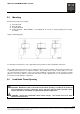
LM16-20-25 I&M MANUAL/EN/11.30.2010 Figure 3. Drive wheel and idler wheel/side plates Adjust drive wheel and idler wheel/side plates as shown above. 5.3 Electric Swivel Trolley Figure 4. Electric swivel trolley Table 1. Electric swivel trolley HOIST TYPE SWIVELING TROLLEY TYPE CAPACITY NUMBER OF WHEELS WHEEL DIAMETER MOTOR TYPE C05 SWIV32 0 – 1 ton 4 100 2 x TMU 1 (35 Hz) C10 SWIV32 0 – 2 tons 4 100 2 x TMU 2 (100 Hz) C16-20-25 SWIV32 0 – 3.
LM16-20-25 I&M MANUAL/EN/11.30.2010 5.3.1 Swiveling trolley (3.2 tons) Figure 5. Swiveling trolley (3.2 tons) - CAPACITY MAX 3.2 TONS (3200 KG) - RAY OF CURVE MINI 2.6 FEET 5.3.2 Swiveling trolley (3.2 to 5.0 tons) (NOT LOCALLY AVAILABLE) Figure 6. Swiveling trolley (3.2 to 5.0 tons) - CAPACITY MAX 3.2 TO 5 TONS (3200 TO 5000 KG) - RAY OF CURVE MINI 3.9 FEET 19/73 This document and the information contained herein, is the exclusive property of R&M Materials Handling, Inc.
LM16-20-25 I&M MANUAL/EN/11.30.2010 5.3.3 Procedure to adjust swivel trolley guide rollers 1. 2. 3. 4. 5. 6. Loosen nut “A” (8 plcs). Adjust guide rollers the maximum distance away from beam. Place swivel trolley on beam. Move trolley to curve section of beam. Adjust guide rollers allowing approximately 3/16” (4-5 mm) clearance per side using screw “B.” Tighten nut “A” (8 plcs). Figure 7. Swivel trolley guide rollers NOTE: Adjustments should be made with swivel trolley in radius of monorail.
LM16-20-25 I&M MANUAL/EN/11.30.2010 6 MAINTENANCE 6.1 Basic Hoist Construction Figure 8. Basic Hoist Components 1 2 7 3 6 4 P 25010 1. 2. 3. 4. 5. 6. 7. 5 TOP HOOK HOIST MOTOR GEAR CASE & GEARING LOAD BLOCK ASSEMBLY CHAIN CONTAINER CHAIN SPROCKET CONTROLS & ENCLOSURE 21/73 This document and the information contained herein, is the exclusive property of R&M Materials Handling, Inc.
LM16-20-25 I&M MANUAL/EN/11.30.2010 6.2 Hoist Motor and Brake Assembly The hoist motors are designed to provide dependable hoisting service. The standard motors are enclosed for IP55 rated protection against normal hazards of dust and moisture. The motor bearings are sealed and do not require further greasing. m DANGER: Before installing, removing, inspection, or performing any maintenance on a hoist, the main switch shall be de-energized.
LM16-20-25 I&M MANUAL/EN/11.30.2010 Remove Hoist Motor and Brake Assembly (refer to Figure 9) 1. Remove load from load block assembly. 2. Raise load block assembly to hoist body. Allow slack in chain to permit tying up bottom block assembly to remove weight of bottom block assembly from load chain. 3. Remove and lockout power to the hoist. 4. Remove three-sided branding cover. 5. Remove three (3) screws (item 1) and take off Brake and Fan Cover (item 2). 6.
LM16-20-25 I&M MANUAL/EN/11.30.2010 Hoist Motor Brake The hoist motor brake is a D.C. electromagnetic disc brake and does not require adjustment. The brake brings the load to a smooth and quick stop and holds the load when the hoist motor is not energized. An energized coil releases the hoist motor brake and permits the raising and lowering of the load. Figure 10. Hoist Motor Brake 8 7 1. 2. 3. 4. 5. 6. 7. 8.
LM16-20-25 I&M MANUAL/EN/11.30.2010 6.2.1 Replacement Criteria for Motor Brakes Table 2. Replacement Criteria for Motor Brakes THICKNESS AS NEW REPLACE WHEN LM 01 LM 05 0.260 inches (6.6 mm) 0.370 inches (9.4 mm) 0.220 inches (5.6 mm) 0.330 inches (8.4 mm) LM 10 LM 16 LM 20 LM 25 0.055 inches 0.406 inches 0.406 inches 0.406 inches 0.016 inches 0.366 inches 0.366 inches 0.366 inches LM 01/ 05/10 MODELS (1.4 mm) (10.3 mm) (10.3 mm) (10.3 mm) (0.4 mm) (9.3 mm) (9.3 mm) (9.
LM16-20-25 I&M MANUAL/EN/11.30.2010 NOTE: MAXIMUM ALLOWABLE GAP IS 0.5mm or 0.020 inches. Remove round plastic dust cap on the side of the brake assembly. Turn off power to hoist, insert gage pin of proper diameter to check motor brake gap. Recommend that a gage pin set be available with increments of 0.001” ranging from 0.015” to 0.020”. The air gap of the brake cannot be adjusted. If the brake air gap is measured above maximum allowable, then he linings must be replaced.
LM16-20-25 I&M MANUAL/EN/11.30.2010 6.3 Torque Limiter (Refer to Figure 11) The hoist is equipped with a torque limiter that is located in the gearbox assembly. The torque limiter is a safety device that prevents lifting excessive loads that may damage to the hoist. The torque limiter is a friction type slip clutch that couples the motor to the gear train. Torque Limiter Adjustment (Refer to Figure 11) 1. 2. 3. 4. 5. 6. 7. 8. 9. 10. Remove three-sided branding panel.
LM16-20-25 I&M MANUAL/EN/11.30.2010 6.4 m 6.5 Load Chain CAUTION: A hoist SHALL NEVER be used if the load chain shows any evidence of mechanical damage or excessive wear. Never use the load chain as a sling. Use only original equipment chain as supplied by a factory authorized source. Improper load chain storage or installation can render the load chain unusable prior to the first lift.
LM16-20-25 I&M MANUAL/EN/11.30.2010 Figure 12. Chain Dimensions t 11 t t Ød P25004 Measure the following chain dimensions at several points on chain: (Figure 12) Dimensions of one link ( d x t ) where, d = diameter and t = pitch Length over 11 links ( 11 t ) Replace load chain if any one of these dimensions exceeds maximum allowed wear: Maximum allowed wear: LM 16 LM 20 / 25 9.0 x 27.0 chain 11.3 x 31.0 Minimum link diameter allowed (d): 0.319” [8.1 mm] 0.398” [10.
LM16-20-25 I&M MANUAL/EN/11.30.2010 6.6 Load Chain Specifications (see Figure 12) Table 3. Load Chain Specifications Hoist Type: LM 16 LM 20/LM25 Chain Specification: Chain type: Diameter (ød) x pitch (t): Load chain - 9.0 x 27.0 Standard 0.3543 x 1.0629 in [9.0 x 27.0 mm] 11.6929” [297 mm] DAT H8S or HE G80 RAS 2 123.4 N/mm 580 or 700 HV 0.18 to 0.45 mm DIN 5684 – 8 1 or 16 H 8 S or A 8 3527 lbs. [1600 kg] Load chain - 11.3 x 31.0 Standard 0.4449 x 1.2205 in [11.3 x 31.0 mm] 13.
LM16-20-25 I&M MANUAL/EN/11.30.2010 6.8 Installing the Load Chain Figure 13. Chain Installation Figure 13-A. Chain Orientation 1-FALL CHAIN INSTALLATION 1. 2. 3. 4. Obtain an electric wire approximately 20 inches (50 cm) in length. Insert the wire into the chain guide and push it through to the other side of the guide. Hook the chain onto the end of the electric wire on the chain container side. Pull on the wire to bring the chain into contact with the chain wheel.
LM16-20-25 I&M MANUAL/EN/11.30.2010 2-FALL CHAIN INSTALLATION 1. 2. 3. 4. Obtain an electric wire approximately 20 inches (50 cm) in length. Insert the wire into the chain guide and push until it through to the other side of the guide. Hook the chain onto the end of the electric wire on the chain container side. Pull on the wire to bring the chain into contact with the chain wheel. Refer to Figure 13-A for chain orientation.
LM16-20-25 I&M MANUAL/EN/11.30.2010 6.9 Fall Stop Assembly (Refer to Figure 14) The slack fall stop is a safety stop, not a functional stop. The fall stop must be located at least six (6.0) inches [150mm] from end of last chain link. Figure 14. Cross Section of Slack Fall Stop P25019 LM 16 LM 20 / 25 Removing Fall Stop Assembly 1. 2. 3. 4. Loosen and remove nut (two each for LM 20/25) Remove bolts. Remove two halves of Fall Stop. Remove limit switch washer plate and spring.
LM16-20-25 I&M MANUAL/EN/11.30.2010 6.10 Chain Container Figure 15. Chain Container Installation m CAUTION: Chain container must be in installed for effective operation of hoisting limit switch. Removing Chain Container (Figure 15) 1. Remove load from load block assembly. 2. Lower load block assembly to until a lowest point. This will remove weight of chain from chain container. 3. Support chain container before removing chain. 4. Remove snap ring (item 3) from end of pin (item 1).
LM16-20-25 I&M MANUAL/EN/11.30.2010 6.11 Upper and Lower Travel Safety Limit Switch The Upper and Lower Travel Limit Switch is an automatic reset type switch and connected to the control circuit. The switch housing is recessed into the underside of hoist body. m CAUTION: The primary limit device that controls the upper limit of travel is an emergency device only. It shall not be used as an operational means to stop travel during normal operations.
LM16-20-25 I&M MANUAL/EN/11.30.2010 6.12 Upper and Lower Rotary Travel Limit Switch The rotary limit switch is adjustable and provides over-travel protection for the upper and lower limits of hoist travel. The limit switch is connected to the control circuit. Note: Rotary limit switch assembly cannot be added to a Hoist. The Hoist must have the rotary limit switch assembly provided at time of initial production.
LM16-20-25 I&M MANUAL/EN/11.30.2010 6.13 Hooks Check hooks for deformation or cracks. Hooks must be replaced if throat opening has increased by more than 15%, or if throat opening has more than 10-degree twist from plane of straight hook. Figure 16. Measuring Hook Deformation Due to many types and sizes of hooks that can be furnished and/or specified by the user / owner, it is recommended that user / owner measure the actual throat opening of hook as originally furnished. See Figure 16.
LM16-20-25 I&M MANUAL/EN/11.30.2010 6.14 Hook Inspection The wear on the top hook and the load hook shall be checked routinely. Measure the throat opening (dimension a2). If the throat opening exceeds the maximum opening allowed (1.15 x a2), replace the hook. Damaged safety latches shall be replaced immediately. Maximum throat opening allowed: Hook class: 05T 08T 1T 16T Top Hook Maximum allowed opening: 1.54” [39mm] 1.69” [43mm] 1.81” [46mm] 2.01” [51mm] 2.
LM16-20-25 I&M MANUAL/EN/11.30.2010 6.15 Hook Dimensions Figure 17. Hook Dimensions TOP HOOK LOAD HOOK Table 4. Hook Dimensions Hook Data Dimensions inch / [mm] Cap Ton Cap kg Test lbs Hoist Fall Hook Class øM ø a1 øa2 a3 b1 b2 e1 h1 h2 t1 t2 øa2 max 1 1/2 1600 7055 LM 16 1 05 T 0.787 [20] 1.693 [43] 1.339 [34] 1.929 [49] 1.412 [29] 0.945 [24] 4.134 [105] 1.457 [37] 1.220 [31] 1.693 [43] 0.551 [14] 1.535 [39] 2 2000 8818 LM 20 1 08 T 0.945 [24] 1.890 [48] 1.
LM16-20-25 I&M MANUAL/EN/11.30.2010 6.16 Top Hook Figure 18. Top Hook Orientation CHAIN CONTAINER BRACKET P25020 m CAUTION: Before removing Top Hook, de-energize the power to the hoist per ANSI Z244.1 and make certain that any load is removed from the load hook. Also support the total weight of the hoist, including chain, prior to removing the Top Hook. Removing Top Hook 1. Place hoist on workbench. Protect limit switches on bottom of hoist. 2. There are two pins holding top hook in place.
LM16-20-25 I&M MANUAL/EN/11.30.2010 6.17 Controls The two-speed hoists are available for 208, 230, 460, 575 Volt - three-phase – 60 hertz power supplies. The controls of the two-speed hoists are NOT re-connectable because the hoist motors are voltage specific. Note: The controls of the motorized trolley drive are not voltage re-connectable. Consult the motorized trolley manual if a voltage changeover is required.
LM16-20-25 I&M MANUAL/EN/11.30.2010 Control Panel Layout Figure 19. Printed Control Circuit (2 Lifting Speeds with Emergency Stop) 42/73 This document and the information contained herein, is the exclusive property of R&M Materials Handling, Inc., and represents a non-public, confidential and proprietary trade secret that may not be reproduced, disclosed to third parties, altered or otherwise employed in any manner whatsoever without the express written consent of R&M Materials Handling, Inc.
LM16-20-25 I&M MANUAL/EN/11.30.2010 6.18 Two Speed – Three Phase – 208 / 230 / 460 Volt – Power Circuit 43/73 This document and the information contained herein, is the exclusive property of R&M Materials Handling, Inc., and represents a non-public, confidential and proprietary trade secret that may not be reproduced, disclosed to third parties, altered or otherwise employed in any manner whatsoever without the express written consent of R&M Materials Handling, Inc.
LM16-20-25 I&M MANUAL/EN/11.30.2010 6.19 Two Speed – Three Phase – 208 / 230 / 460 Volt – Control Circuit 44/73 This document and the information contained herein, is the exclusive property of R&M Materials Handling, Inc., and represents a non-public, confidential and proprietary trade secret that may not be reproduced, disclosed to third parties, altered or otherwise employed in any manner whatsoever without the express written consent of R&M Materials Handling, Inc.
LM16-20-25 I&M MANUAL/EN/11.30.2010 6.20 Two Speed – Three Phase – 575 Volt – Power Circuit 45/73 This document and the information contained herein, is the exclusive property of R&M Materials Handling, Inc., and represents a non-public, confidential and proprietary trade secret that may not be reproduced, disclosed to third parties, altered or otherwise employed in any manner whatsoever without the express written consent of R&M Materials Handling, Inc. Copyright © (2010) R&M Materials Handling, Inc.
LM16-20-25 I&M MANUAL/EN/11.30.2010 6.21 Two Speed – Three Phase – 575 Volt – Control Circuit 46/73 This document and the information contained herein, is the exclusive property of R&M Materials Handling, Inc., and represents a non-public, confidential and proprietary trade secret that may not be reproduced, disclosed to third parties, altered or otherwise employed in any manner whatsoever without the express written consent of R&M Materials Handling, Inc. Copyright © (2010) R&M Materials Handling, Inc.
LM16-20-25 I&M MANUAL/EN/11.30.2010 6.22 Wiring Diagram – 3 Button – Push Button 47/73 This document and the information contained herein, is the exclusive property of R&M Materials Handling, Inc., and represents a non-public, confidential and proprietary trade secret that may not be reproduced, disclosed to third parties, altered or otherwise employed in any manner whatsoever without the express written consent of R&M Materials Handling, Inc. Copyright © (2010) R&M Materials Handling, Inc.
LM16-20-25 I&M MANUAL/EN/11.30.2010 6.23 Wiring Diagram – 5 Button – Push Button 48/73 This document and the information contained herein, is the exclusive property of R&M Materials Handling, Inc., and represents a non-public, confidential and proprietary trade secret that may not be reproduced, disclosed to third parties, altered or otherwise employed in any manner whatsoever without the express written consent of R&M Materials Handling, Inc. Copyright © (2010) R&M Materials Handling, Inc.
LM16-20-25 I&M MANUAL/EN/11.30.2010 6.24 Wiring Diagram – 7 Button – Push Button 49/73 This document and the information contained herein, is the exclusive property of R&M Materials Handling, Inc., and represents a non-public, confidential and proprietary trade secret that may not be reproduced, disclosed to third parties, altered or otherwise employed in any manner whatsoever without the express written consent of R&M Materials Handling, Inc. Copyright © (2010) R&M Materials Handling, Inc.
LM16-20-25 I&M MANUAL/EN/11.30.2010 7 PREVENTATIVE MAINTENANCE 7.1 Maintenance and Inspection Table Table 7.
LM16-20-25 I&M MANUAL/EN/11.30.2010 7.2 Lubrication Table 8. Lubrication Specifications LUBRICATION POINT Chain SPECIFICATIONS Oil or Liquid grease Idler sprocket Grease (without MoS2) Slide bearing + KP 2 (DIN 51 502) bearing Soap-based lithium Approx.
LM16-20-25 I&M MANUAL/EN/11.30.2010 7.3 Recommended Technical Support for Various Spare Parts Table 9.
LM16-20-25 I&M MANUAL/EN/11.30.2010 7.5 Troubleshooting Table 11.
LM16-20-25 I&M MANUAL/EN/11.30.2010 8 8.1 PARTS ILLUSTRATIONS Hoist Gearbox Components 54/73 This document and the information contained herein, is the exclusive property of R&M Materials Handling, Inc., and represents a non-public, confidential and proprietary trade secret that may not be reproduced, disclosed to third parties, altered or otherwise employed in any manner whatsoever without the express written consent of R&M Materials Handling, Inc. Copyright © (2010) R&M Materials Handling, Inc.
LM16-20-25 I&M MANUAL/EN/11.30.2010 Table 12.
LM16-20-25 I&M MANUAL/EN/11.30.2010 8.2 C16 / C20 / C25 Hoist Motor & Brake Assembly 56/73 This document and the information contained herein, is the exclusive property of R&M Materials Handling, Inc., and represents a non-public, confidential and proprietary trade secret that may not be reproduced, disclosed to third parties, altered or otherwise employed in any manner whatsoever without the express written consent of R&M Materials Handling, Inc. Copyright © (2010) R&M Materials Handling, Inc.
LM16-20-25 I&M MANUAL/EN/11.30.2010 Table 13.
LM16-20-25 I&M MANUAL/EN/11.30.2010 8.3 Lifting Assembly – C16 Only 4d 58/73 This document and the information contained herein, is the exclusive property of R&M Materials Handling, Inc., and represents a non-public, confidential and proprietary trade secret that may not be reproduced, disclosed to third parties, altered or otherwise employed in any manner whatsoever without the express written consent of R&M Materials Handling, Inc. Copyright © (2010) R&M Materials Handling, Inc. All rights reserved.
LM16-20-25 I&M MANUAL/EN/11.30.2010 Table 14.
LM16-20-25 I&M MANUAL/EN/11.30.2010 8.4 Lifting Assembly – C20/25 Only 4d 60/73 This document and the information contained herein, is the exclusive property of R&M Materials Handling, Inc., and represents a non-public, confidential and proprietary trade secret that may not be reproduced, disclosed to third parties, altered or otherwise employed in any manner whatsoever without the express written consent of R&M Materials Handling, Inc. Copyright © (2010) R&M Materials Handling, Inc.
LM16-20-25 I&M MANUAL/EN/11.30.2010 Table 15.
LM16-20-25 I&M MANUAL/EN/11.30.2010 8.5 C16 / C20 / C25 Electrical Control Assembly 62/73 This document and the information contained herein, is the exclusive property of R&M Materials Handling, Inc., and represents a non-public, confidential and proprietary trade secret that may not be reproduced, disclosed to third parties, altered or otherwise employed in any manner whatsoever without the express written consent of R&M Materials Handling, Inc. Copyright © (2010) R&M Materials Handling, Inc.
LM16-20-25 I&M MANUAL/EN/11.30.2010 Table 16.
LM16-20-25 I&M MANUAL/EN/11.30.2010 8.6 Double Brake (Option) C16 / C20 / C25 7 2 6A – 6B 1 5 4 3 Table 17. C16/C20/C25 Double Brake Option Parts List ITEM PART NUMBER DESCRIPTION QTY 1 52336943 COMPLETE BOX FOR LOW VOLTAGE 1 2 52338342 SUPPORT BOX ASSY FOR LOW VOLTAGE 1 3 52337007 BRAKE ASSEMBLY 1 4 52336944 COMPLETE MAGNET BOX 1 5 52335461 MAGNET ONLY 1 6A 52337909 GEAR C25 GE25-4 6.3/1.
LM16-20-25 I&M MANUAL/EN/11.30.2010 THIS PAGE INTENTIONALLY LEFT BLANK 65/73 This document and the information contained herein, is the exclusive property of R&M Materials Handling, Inc., and represents a non-public, confidential and proprietary trade secret that may not be reproduced, disclosed to third parties, altered or otherwise employed in any manner whatsoever without the express written consent of R&M Materials Handling, Inc. Copyright © (2010) R&M Materials Handling, Inc. All rights reserved.
LM16-20-25 I&M MANUAL/EN/11.30.2010 8.7 Electric trolley (Swiveling trolley 0 to 3.2 Tons (3200 Kg)) Figure 20. Electric trolley (swiveling trolley 0 to 3.2 tons (3200 Kg)) 5 NOTE: ECH is attached to swivel trolley through a mechanical connection. No top hook connection available. 66/73 This document and the information contained herein, is the exclusive property of R&M Materials Handling, Inc.
LM16-20-25 I&M MANUAL/EN/11.30.2010 Table 18. Electric trolley (Swiveling trolley 0 to 3.2 Tons (3200 Kg)) ITEM DESCRIPTION Complete 2-speed motor drive 115Vc 460V 575V ≤ 3.2 Ton (3200 Kg) 208/230V 1 Complete inverter motor drive 115Vc 460V 575V 208/230V ≤ 1 Ton (1000 Kg) > 1 Ton ≤ 3.2 Ton QTY CODE 2 52306026 2 52306027 2 52306028 2 52299090 2 52304881 2 Idler side plate 2 52326596 3 Drive side plate 2 52326597 Swivel CHRD Kit 2.60 – 4.33 in.
LM16-20-25 I&M MANUAL/EN/11.30.2010 8.8 Push Button Assembly – Horizontal Pairs of Buttons Table 19.
LM16-20-25 I&M MANUAL/EN/11.30.2010 8.9 Push Button Assembly – Horizontal Pairs of Buttons 1 3 2 Table 20.
LM16-20-25 I&M MANUAL/EN/11.30.2010 8.10 Push Button Assembly – Vertical Pairs of Buttons (Option) 70/73 This document and the information contained herein, is the exclusive property of R&M Materials Handling, Inc., and represents a non-public, confidential and proprietary trade secret that may not be reproduced, disclosed to third parties, altered or otherwise employed in any manner whatsoever without the express written consent of R&M Materials Handling, Inc.
LM16-20-25 I&M MANUAL/EN/11.30.2010 Table 21.
LM16-20-25 I&M MANUAL/EN/11.30.2010 8.11 Push Button Assembly – Vertical Buttons (Option) Table 22.
LM16-20-25 I&M MANUAL/EN/11.30.2010 THIS PAGE INTENTIONALLY LEFT BLANK 73/73 This document and the information contained herein, is the exclusive property of R&M Materials Handling, Inc., and represents a non-public, confidential and proprietary trade secret that may not be reproduced, disclosed to third parties, altered or otherwise employed in any manner whatsoever without the express written consent of R&M Materials Handling, Inc. Copyright © (2010) R&M Materials Handling, Inc. All rights reserved.