
Manual


LM10 I&M MANUAL/EN/11.30.2010
42/85
This document and the information contained herein, is the exclusive property of R&M Materials Handling, Inc., and represents a non-public, confidential and proprietary trade secret
that may not be reproduced, disclosed to third parties, altered or otherwise employed in any manner whatsoever without the express written consent of R&M Materials Handling, Inc.
Copyright © (2010) R&M Materials Handling, Inc. All rights reserved.
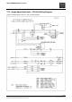
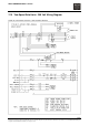
208 / 230 VOLT (SEE 208/230 VOLT SINGLE SPEED CONTROL LAYOUT & WIRING DIAGRAM)
1. Connect motor brake lead (-) to terminal strip X1 terminal 14. Connect (+) to K21 terminal 4.
2. Motor Leads:
a. T1 & T7 connect to main line contactor K10 terminal 1.
b. T2 & T8 connect to DOWN contactor K22 terminal 2.
c. T3 & T9 connect to DOWN contactor K22 terminal 6.
d. T4 connect to terminal strip X1 terminal 11.
e. T5 connect to terminal strip X1 terminal 12.
f. T6 connect to terminal strip X1 terminal 13.
g. Jumper wires on terminal strip X1 to connect terminals 11, 12, and 13.
3. Control transformer connections:
a. Jumper connections terminals 230 to 230 and terminals 01 to 02. See control panel layouts and
wiring diagrams.
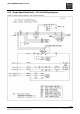
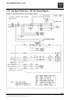
460 VOLT (REFER TO 460 VOLT SINGLE SPEED WIRING DIAGRAM)
1. Connect motor brake lead (-) to contactor K21 terminal 2.
2. Motor leads:
a. T1 connect to main line contactor K10 terminal 1.
b. T2 connect to DOWN contactor K22 terminal 2.
c. T3 connect to DOWN contactor K22 terminal 6.
d. T4 & T7 connect to terminal strip X1 terminal 11.
e. T5 & T8 connect to terminal strip X1 terminal 12.
f. T6 & T9 connect to terminal strip X1 terminal 13.
3. Control transformer connections:
a. Jumper connections for 460 volt (see wiring diagram).
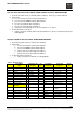
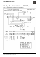
Table 4. Wiring Diagram
Power & Motor
Supply
Pendant Plug X23
Description
Pin
No:
Tag strip X1
Terminal No:
Control Panel
Description
Plug Pin
No:
L1 Hoist power supply Common 1 10 SD: low speed 2
L2 Hoist power supply Hoist UP 2 1 Hoist UP
L3 Hoist power supply Hoist DOWN 3 4 Hoist DOWN
K21-2 + brake Hoist FAST 4 6 D2: Trolley FWD 5
K21-4 - brake Emergency stop 5 7 D1: Trolley REV 4
K10-1 T1, T7 motor supply Trolley FWD 6 8 F: Trolley Fast 3
K22-4 T3, T9 motor supply Trolley REV 7 9 Control voltage 1
K22-6 T2, T8 motor supply Trolley FAST 8 1-2 Thermal protection
X1-11 T4 motor supply 2-3 Upper limit switch
X1-12 T5 motor supply 4-5 Lower limit switch
X1-13 T6 motor supply K10 Mainline contactor
Ground Terminals
Description
K21 Hoist UP contactor
PE Motor K22 Hoist DOWN
Contactor
PE Control panel K25 Hoist FAST
PE Trolley connection T100 Control Transformer
PE Power supply 9 Counter (option)
K22-22 Counter (option)
F100 630 mA