
User Manual

LM01 I&M MANUAL/EN/11.30.2010
38/65
This document and the information contained herein, is the exclusive property of R&M MATERIALS HANDLING, INC. and represents a non-public, confidential and proprietary trade secret
that may not be reproduced, disclosed to third parties, altered or otherwise emplo
yed in any manner whatsoever without the express written consent of R&M MATERIALS HANDLING, INC.
Copyright © (2010) R&M MATERIALS HANDLING, INC. All rights reserved.
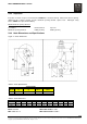
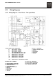
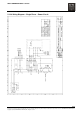
5.12 Wiring Diagrams
5.12.1 Wiring Diagram – Three Phase – Two-speed Hoist
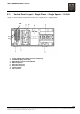
3 PHASE POWER SUPPLY CONNECTIONS PLUG X23 – P/ B CONTROL
L1 HOIST SUPPLY – PHASE A 1 - CONTROL VOLTAGE SUPPLY
L2 HOIST SUPPLY – PHASE B 2 - HOIST UP
L3 HOIST SUPPLY – PHASE C 3 - HOIST DOWN
( - ) HOIST MOTOR BRAKE SUPPLY – VDC 4 - HOIST FAST
( + ) HOIST MOTOR BRAKE SUPPLY - VDC 9 - GROUND
1V MOTOR SUPPLY – SLOW SPEED
2V MOTOR SUPPLY – FAST SPEED
1W MOTOR SUPPLY – SLOW SPEED
2W MOTOR SUPPLY – FAST SPEED
1U2U MOTOR SUPPLY – SLOW AND FAST SPEEDS
TERMINAL STRIP X1 NUMBERS K21 - HOIST “UP” CONTACTOR
K22 - HOIST “DOWN” CONTACTOR
30 - MOTOR THERMAL PROTECTION K25 - HOIST “FAST” CONTACTOR
31 - MOTOR THERMAL PROTECTION F100 - CONTROL CIRCUIT FUSE
22 - UPPER LIMIT SWITCH
23 - LOWER LIMIT SWITCH
1 - CONTROL VOLTAGE SUPPLY
2 - HOIST UP
3 - HOIST DOWN
4 - HOIST FAST
9 - GROUND