
User Manual

LM01 I&M MANUAL/EN/11.30.2010
35/65
This document and the information contained herein, is the exclusive property of R&M MATERIALS HANDLING, INC. and represents a non-public, confidential and proprietary trade secret
that may not be reproduced, disclosed to third parties, altered or otherwise emplo
yed in any manner whatsoever without the express written consent of R&M MATERIALS HANDLING, INC.
Copyright © (2010) R&M MATERIALS HANDLING, INC. All rights reserved.
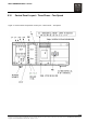
5.9 Controls
5.9.1 General
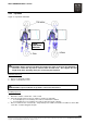
Three-phase, two-speed hoists are available for most three-phase power supply voltages. The controls of
two-speed hoists cannot be connected to more than one power supply voltage.
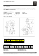
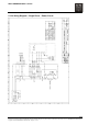
The control panel layouts and wiring diagrams found in this manual are for standard hoist controls. The hoist
motor brake rectifier is part of the PC (printed circuit) board assembly.
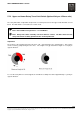
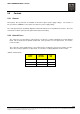
5.9.2 Control Fuses
The control fuse for Three-Phase control panels is located in a vertical, cylindrical fuse holder labeled
F100. This is mounted to the printed circuit board. The top rotates loose for replacement. See Section
5.10 for location.
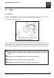
The control fuse for the Single-Phase 115V control panels is installed as an in-line fuse holder on a wire.
The in-line housing separates for replacement. See Section 5.12 wiring diagrams for wire location.
Table 5. Control Fuses
POWER
SUPPLY
CONTROL
VOLTAGE
FUSE
SIZE
3 – PHASE 115 VAC 500 mA
3 – PHASE 48 VAC 630 mA
1 - PHASE 115 VAC 250 mA