INSTALLATION AND MAINTENANCE MANUAL LM CHAIN HOIST LOADMATE® LM1 English STD-R-KHA-F-CQD-ENG This document and the information contained herein, is the exclusive property of R&M Materials Handling, Inc., and represents a non-public, confidential and proprietary trade secret that may not be reproduced, disclosed to third parties, altered or otherwise employed in any manner whatsoever without the express written consent of R&M Materials Handling, Inc. Copyright © (2010) R&M Materials Handling, Inc.
LM01 I&M MANUAL/EN/11.30.2010 THIS PAGE INTENTIONALLY LEFT BLANK 2/65 This document and the information contained herein, is the exclusive property of R&M MATERIALS HANDLING, INC. and represents a non-public, confidential and proprietary trade secret that may not be reproduced, disclosed to third parties, altered or otherwise employed in any manner whatsoever without the express written consent of R&M MATERIALS HANDLING, INC. Copyright © (2010) R&M MATERIALS HANDLING, INC. All rights reserved.
LM01 I&M MANUAL/EN/11.30.2010 m m CAUTION: Read the instructions supplied with the product before installation and commissioning. CAUTION: Keep the instructions in a safe place for future reference. Table of contents 1 2 3 4 5 INTRODUCTION ........................................................................................................................................ 5 1.1 Contact Information .....................................................................................................
LM01 I&M MANUAL/EN/11.30.2010 5.9.2 Control Fuses............................................................................................................................... 35 5.10 Control Panel Layout – Three Phase – Two Speed ........................................................................ 36 5.11 Control Panel Layout – Single Phase – Single Speed – 115 Volt ................................................... 37 5.12 Wiring Diagrams ............................................................
LM01 I&M MANUAL/EN/11.30.2010 1 INTRODUCTION 1.1 Contact Information Please do not hesitate to use the following contact information in the event that you may need assistance: R&M MATERIALS HANDLING, INC. 4501 Gateway Boulevard Springfield, OH 45502 General Telephone: 937 - 328-5100 Toll Free Telephone (US): 800 - 955-9967 General Fax: 937 - 325-5319 Parts Department Fax (US): 800 - 955-5162 Parts Dept. Fax (other): 937 - 328-5162 Website: www.rmhoist.com 1.
LM01 I&M MANUAL/EN/11.30.2010 1.4 Safety Read and understand this manual before using the hoist. Important issues to remember during installation, operation, maintenance, and inspection are provided at the hoist control stations, at various locations on the hoist, in this manual, and in the LoadMate® Electric Chain Hoist Operator’s Manual.
LM01 I&M MANUAL/EN/11.30.2010 The words SHALL and SHOULD are used throughout this manual in accordance with definitions in the ASME B30 standards as follows: SHALL indicates a rule is mandatory and must be followed. SHOULD indicates a rule is a recommendation, the advisability of which depends on the facts in each situation. Hoist operation, hoist inspection, and hoist maintenance personnel training programs should be based on requirements in accordance with the latest edition of: ASME B30.
LM01 I&M MANUAL/EN/11.30.2010 NOTICE: m It is a responsibility of the owner / user to install, inspect, test, maintain, and operate a hoist in accordance with the ASME B30.16 Safety Standard, OSHA Regulations, and ANSI / NFPA 70, National Electric Code. If the hoist is installed as part of a total lifting system, it is also the responsibility of the owner / user to comply with the applicable ASME B30 volume that addresses other types of equipment used in the system.
LM01 I&M MANUAL/EN/11.30.2010 2 INSTALLATION m 2.1 DANGER: Before installing, removing, inspection, or performing any maintenance on a hoist, the main switch shall be de-energized. Lock and tag the main switch in the deenergized position in accordance with ANSI Z244.1. Follow other maintenance procedures outlined in this manual and ASME B30.16. General Prior to installation, the unit shall be checked thoroughly for damage during shipment or handling at the job site.
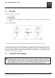
LM01 I&M MANUAL/EN/11.30.2010 2.3 Mounting Below are three types of mounting: 1. 2. 3. 4. Hook Mounted Base Mounted Coupling Mounted Trolley Mounted – NOT SHOWN – is accomplished via a Hook or Trolley Coupling to the Trolley Assembly. Figure 1. Mounting Types For all trolley-mounted hoists, refer to appropriate trolley manual for trolley installation instructions. After a trolley-mounted hoist has been assembled to a beam, check for balance.
LM01 I&M MANUAL/EN/11.30.2010 2.5 Electrical Connection The user / owner must provide the main power supply hardware (cable, conductor bar, fuses, disconnect switch, etc.). m CAUTION: Make sure that the power supply voltage is the same as that shown on hoist serial plate / nameplate. m CAUTION: Make sure that fuses and other current overload devices are in place to protect the power supply.
LM01 I&M MANUAL/EN/11.30.2010 2.6 Three Phase Power Connections Figure 2. Three Phase Control Box Power Connections 1. 2. 3. 4. 5. 6. 7. 8. Remove control box cover. Insert power supply cable through cable gland or assemble to (optional) plug. Connect power leads L1, L2, and L3 to relay K21. Connect ground wire PE (GRD) to terminal strip (2). Refer to wiring diagram. Tighten terminal screws. Tighten cable gland or (optional) connector to secure power cable. Replace control box cover.
LM01 I&M MANUAL/EN/11.30.2010 2.7 Single Phase Power Connections Figure 3. Single Phase Control Box Power Connections PE L1 L2 POWER CABLE PUSHBUTTON PLUG GLAND 1. 2. 3. 4. 5. 6. 7. 8. Remove control box cover. Insert power supply cable through power cable gland (Figure 3). Connect power leads L1 and L2 to terminal strip (Figure 3). Connect ground wire PE to terminal strip (Figure 3). Refer to wiring diagram.
LM01 I&M MANUAL/EN/11.30.2010 3 INITIAL START-UP m 3.1 WARNING: Before connecting power to hoist, check all “motion” buttons on pendant control assembly to make sure that they operate freely without binding or sticking. Check pendant cable and strain relief connection to ensure that they are not damaged. General Initial start-up procedures are as follows: Read all attached WARNING tags and placards affixed to hoist. Oil load chain generously over entire length of chain.
LM01 I&M MANUAL/EN/11.30.2010 3.3 Check hoist motor brake function. Run empty load block up or down to check that load block does not drift more than 1.0 inch [25mm]. If so, adjust brake as described in Section 5.3 of this manual. Run empty load block down to check that fall stop (located on free end of load chain) makes proper contact with upper / lower travel safety limit switch and that limit switch functions properly.
LM01 I&M MANUAL/EN/11.30.2010 4 HOIST OPERATION m m m WARNING: BEFORE PROCEEDING WITH THE NORMAL OPERATION OF THIS HOIST, THE OPERATOR/(S) SHALL BE TRAINED IN ACCORDANCE WITH THE LoadMate® Electric Chain Hoist Operator’s Manual AS SUPPLIED WITH THIS HOIST.
LM01 I&M MANUAL/EN/11.30.2010 5 MAINTENANCE 5.1 Basic Hoist Construction Figure 4. Basic Hoist Components 1. 2. 3. 4. 5. 6. 7. 8. 9. 10. 5.2 LOAD BLOCK ASSEMBLY (2-FALL SHOWN) LOAD CHAIN ELECTRICAL CONTROL ENCLOSURE TOP HOOK HOIST GEAR BOX ASSEMBLY CHAIN CONTAINER & HARDWARE HOIST BODY / MOTOR LOAD HOOK SAFETY LATCH CLIP (ONE EACH END) PIN Motor / Body The hoist motors are designed to provide dependable hoisting service.
LM01 I&M MANUAL/EN/11.30.2010 5.3 Hoist Motor Brake and Load-Limiting Device The hoisting motor is equipped with a D.C. electromagnetic disc brake. The brake brings the load to a smooth and quick stop and holds the load when the motor is not energized. An energized coil releases the hoist brake to allow the hoisting motor to run freely when in use. The load-limiting device is a slip clutch and it is integrated into the design of the hoist motor brake.
LM01 I&M MANUAL/EN/11.30.2010 Figure 5. Cross Section of Hoist Brake / Slip Clutch 7 X 6 5 11 12 1 8 9 10 4 3 2 P01017 Table 1. Hoist Brake / Slip Clutch Parts List ITEM DESCRIPTION 1 ELECTROMAGNETIC COIL 2 BRAKE LINING PLATE 3 BRAKE AND SLIP CLUTCH DISC 4 SLIP CLUTCH LINING DISC 5 SCREWS 6 SLEEVE 7 ELASTIC WASHERS 8 MOTOR SHAFT 9 ADJUSTING NUT 10 SPRING 11 GEAR COVER 12 BEARING NOTE: Item ‘X’ (air gap) is discussed in section 5.3.3 Hoist Motor Brake Adjustment.
LM01 I&M MANUAL/EN/11.30.2010 m SEE Figure 5 CAUTION: Make sure the motor is not running before placing tool on the nut to adjust it. Do not touch any moving components. m m CAUTION: The slip-clutch generates heat when slipping. ITEMS 3 & 4 absorb this heat. When these items become too hot, clutch adjustment may be difficult due to unstable behavior of friction surfaces. If this happens, allow brake & clutch assembly to cool before trying to re-adjust slip-clutch.
LM01 I&M MANUAL/EN/11.30.2010 5.3.3 Hoist Motor Brake Adjustment (See Figure 5) If maximum air gap of brake has been reached or will be exceeded before next inspection, readjust air gap. Minimum air gap Maximum air gap X = 0.006” [ 0.15 mm ] X = 0.020” [ 0.5 mm ] Before adjusting brake, remove load. Per ANSI Z244.1, lockout and tag main disconnect switch in deenergized position. Follow other maintenance procedures outlined in this manual and ASME B30.16. 1. Remove brake cover and gasket. 2.
LM01 I&M MANUAL/EN/11.30.2010 5.3.4 Replacement Criteria for Motor Brakes Table 2. Replacement Criteria for Motor Brakes LM LM LM LM LM 01 05 10 16 20 LM 25 THICKNESS AS NEW REPLACE WHEN 0.260 inches 0.370 inches 0.055 inches 0.406 inches 0.406 inches 0.220 inches 0.330 inches 0.016 inches 0.366 inches 0.366 inches (6.6 mm) (9.4 mm) (1.4 mm) (10.3 mm) (10.3 mm) 0.406 inches (10.3 mm) LM 01 / 05 / 10 MODELS (5.6 mm) (8.4 mm) (0.4 mm) (9.3 mm) (9.3 mm) 0.366 inches (9.
LM01 I&M MANUAL/EN/11.30.2010 5.4 5.4.1 m 5.4.2 Load Chain General CAUTION: A hoist SHALL NEVER be used if the load chain shows any evidence of mechanical damage or excessive wear. Never use the load chain as a sling. Use only original equipment chain as supplied by a factory authorized source. Improper load chain storage or installation can render the load chain unusable prior to the first lift.
LM01 I&M MANUAL/EN/11.30.2010 Measure the following chain dimensions at several points on chain: (Figure 6) Dimensions of one link ( d x t ) where, d = diameter and t = pitch Length over 11 links ( 11 t ) Replace load chain if any one of these dimensions exceeds maximum allowed wear. Maximum allowed wear: Minimum link diameter allowed (d): 0.1102” [2.8 mm] Maximum pitch allowed (t): 0.3839” [9.75 mm] Maximum length allowed (11t): 4.1063” [104.
LM01 I&M MANUAL/EN/11.30.2010 5.4.3 Load Chain Specifications (see Figure 6) Chain use: Load chain Chain type: Standard - Galvanized Size: (d) diameter x (t) pitch: 0.122” [3.1 mm] / 0.366” [9.3 mm] Class: DAT Grade: H8S or HE G80 RAS Maximum working stress: 14,516.1 lbs / in [100 N / mm ] Hardened surface: 580 to 700 HV [Vickers Hardness] Thickness: 0.0039” [0.1 mm] to 0.0079” [0.
LM01 I&M MANUAL/EN/11.30.2010 5.4.5 Installing the Load Chain Figure 7. Chain Installation Figure 7-A. Chain Orientation 1-FALL CHAIN INSTALLATION 1. Attach last link of chain onto hook of CHAIN INSERTION TOOL (item 1, Figure 7). 2. If the insertion tool is not in the hoist (removal procedure), insert other end of CHAIN INSERTION TOOL into chain opening closest to chain container side. m CAUTION: Make sure the chain weld on chain link faces inward toward chain wheel pocket on hoist load sprocket.
LM01 I&M MANUAL/EN/11.30.2010 2-FALL CHAIN INSTALLATION 1. If the chain insertion tool is not in the hoist (removal procedure), attach last link of chain onto hook of CHAIN INSERTION TOOL (item 1, Figure 7). 2. Insert other end of CHAIN INSERTION TOOL into chain opening closest to chain container. m CAUTION: For a 2-Fall load block assembly, make sure the chain weld on chain link faces inward toward chain wheel pocket on hoist and away from idler sprocket of hook block assembly. See figure 7-A.
LM01 I&M MANUAL/EN/11.30.2010 5.5 Fall Stop Assembly 5.5.1 General The slack fall stop is a safety stop, not a functional stop. The fall stop must be located at least six (6.0) inches [150mm] from end of last chain link. Figure 8. Cross Section of Slack Fall Stop 5.5.2 Fall Stop Installation 1. Position two fall stop halves (item 1, Figure 8) on chain link at least six (6.0”) inches [150mm] from end of load chain. 2. Insert screw (item 2) through fall stop halves and chain link. 3.
LM01 I&M MANUAL/EN/11.30.2010 5.6 Chain Container Figure 9. Chain Container Installation m CAUTION: Chain container must be installed for effective operation of travel limit switch. Removing Chain Container 1. Remove clip (item 3) from end of pin (item 2). 2. Pull pin (item 2) out while supporting chain container (item 1) at same time. 3. Remove chain container. Installing Chain Container 1. Insert load chain into chain container (item 1) and position chain container on mounting bracket. 2.
LM01 I&M MANUAL/EN/11.30.2010 5.7 Limit Switches 5.7.1 Upper and Lower Travel Safety Limit Switch The Upper and Lower Travel Limit Switch is an automatic reset type switch and connected to the control circuit. The switch housing is recessed into the underside of hoist body. The upper and lower limit switches are emergency protection devices and are not to be used as a continuous stop.
LM01 I&M MANUAL/EN/11.30.2010 5.7.2 Upper and Lower Rotary Travel Limit Switch (Optional Only on 3-Phase units) The rotary limit switch is adjustable and provides over-travel protection for the upper and lower limits of hoist travel. The limit switch is connected to the control circuit. Note: Not available on Single Phase – 115 Volt Models Note: Rotary limit switch assembly cannot be added to a Hoist. The Hoist must have the rotary limit switch assembly provided at time of initial production.
LM01 I&M MANUAL/EN/11.30.2010 5.8 Hooks 5.8.1 General Check hooks for deformation or cracks. Hooks must be replaced if throat opening has increased by more than 15%, or if throat opening has more than 10-degree twist from plane of straight hook. Figure 10. Measuring Hook Deformation Due to many types and sizes of hooks that can be furnished and/or specified by the user / owner, it is recommended that user / owner measure the actual throat opening of hook as originally furnished. See Figure 10.
LM01 I&M MANUAL/EN/11.30.2010 5.8.2 Inspection Inspection for wear on top hook and load hook SHALL be checked routinely. Measure the throat opening. (dimension-a2). If throat opening exceeds maximum opening allowed, replace hook. Damaged safety latches SHALL be replaced immediately. Maximum throat opening allowed: Hook Class: Maximum opening allowed: 012P load hook 0.906” [23 mm] top hook 0.906” [23 mm] 5.8.3 Hook Dimensions and Specifications Figure 11. Hook Dimensions Table 3.
LM01 I&M MANUAL/EN/11.30.2010 5.8.4 Top Hook Figure 12. Top Hook Orientation CHAIN CONTAINER BRACKET m CAUTION: Before removing Top Hook, de-energize the power to the hoist per ANSI Z244.1 and make certain that any load is removed from the load hook. Also support the total weight of the hoist, including chain, prior to removing the Top Hook. Removing Top Hook 1. Remove locking plate and pin. 2. Pull pin out and remove hook. m CAUTION: Proper installation of top hook is critical for hoist balance.
LM01 I&M MANUAL/EN/11.30.2010 5.9 Controls 5.9.1 General Three-phase, two-speed hoists are available for most three-phase power supply voltages. The controls of two-speed hoists cannot be connected to more than one power supply voltage. The control panel layouts and wiring diagrams found in this manual are for standard hoist controls. The hoist motor brake rectifier is part of the PC (printed circuit) board assembly. 5.9.
LM01 I&M MANUAL/EN/11.30.2010 5.10 Control Panel Layout – Three Phase – Two Speed Figure 13. Control Panel Components and Layout – Three Phase – Two Speed 36/65 This document and the information contained herein, is the exclusive property of R&M MATERIALS HANDLING, INC.
LM01 I&M MANUAL/EN/11.30.2010 5.11 Control Panel Layout – Single Phase – Single Speed – 115 Volt Figure 14. Control Panel Components and Layout – Single Phase – Single Speed PE L1 L2 1. 2. 3. 4. 5. 6. 7. 8.
LM01 I&M MANUAL/EN/11.30.2010 5.12 Wiring Diagrams 5.12.
LM01 I&M MANUAL/EN/11.30.2010 5.12.2 Wiring Diagram – Single Phase – Connections and Components Connections, Terminals, and Components for Single Phase L1 – SINGLE PHASE POWER SUPPLY L2 – SINGLE PHASE NEUTRAL PE – GROUND - – MOTOR BRAKE SUPPLY + – MOTOR BRAKE SUPPLY U1V1 – MOTOR SUPPLY U2 – MOTOR “UP” V2 – MOTOR “DOWN” X23 – PUSHBUTTON CONTROL ASSEMBLY PLUG X22 – OPTIONAL POWER SUPPLY PLUG NOTE: ROTARY LIMIT SWITCH IS NOT AVAILABLE FOR SINGLE PHASE UNITS.
LM01 I&M MANUAL/EN/11.30.2010 5.12.3 Wiring Diagram – Single Phase – Power Circuit 40/65 This document and the information contained herein, is the exclusive property of R&M MATERIALS HANDLING, INC. and represents a non-public, confidential and proprietary trade secret that may not be reproduced, disclosed to third parties, altered or otherwise employed in any manner whatsoever without the express written consent of R&M MATERIALS HANDLING, INC. Copyright © (2010) R&M MATERIALS HANDLING, INC.
LM01 I&M MANUAL/EN/11.30.2010 5.12.4 Wiring Diagram – Single Phase – Control Circuit 41/65 This document and the information contained herein, is the exclusive property of R&M MATERIALS HANDLING, INC. and represents a non-public, confidential and proprietary trade secret that may not be reproduced, disclosed to third parties, altered or otherwise employed in any manner whatsoever without the express written consent of R&M MATERIALS HANDLING, INC. Copyright © (2010) R&M MATERIALS HANDLING, INC.
LM01 I&M MANUAL/EN/11.30.2010 5.12.5 Wiring Diagram – 3 Button – Push Button 42/65 This document and the information contained herein, is the exclusive property of R&M MATERIALS HANDLING, INC. and represents a non-public, confidential and proprietary trade secret that may not be reproduced, disclosed to third parties, altered or otherwise employed in any manner whatsoever without the express written consent of R&M MATERIALS HANDLING, INC. Copyright © (2010) R&M MATERIALS HANDLING, INC.
LM01 I&M MANUAL/EN/11.30.2010 5.12.6 Wiring Diagram – 5 Button – Push Button 43/65 This document and the information contained herein, is the exclusive property of R&M MATERIALS HANDLING, INC. and represents a non-public, confidential and proprietary trade secret that may not be reproduced, disclosed to third parties, altered or otherwise employed in any manner whatsoever without the express written consent of R&M MATERIALS HANDLING, INC. Copyright © (2010) R&M MATERIALS HANDLING, INC.
LM01 I&M MANUAL/EN/11.30.2010 5.12.7 Wiring Diagram – 7 Button – Push Button 44/65 This document and the information contained herein, is the exclusive property of R&M MATERIALS HANDLING, INC. and represents a non-public, confidential and proprietary trade secret that may not be reproduced, disclosed to third parties, altered or otherwise employed in any manner whatsoever without the express written consent of R&M MATERIALS HANDLING, INC. Copyright © (2010) R&M MATERIALS HANDLING, INC.
LM01 I&M MANUAL/EN/11.30.2010 6 PREVENTATIVE MAINTENANCE 6.1 Maintenance and Inspection Table Table 6.
LM01 I&M MANUAL/EN/11.30.2010 6.2 Lubrication OPEN WHEEL GEARING: MOBILUX EP1 OR EQUIVALENT Table 7.
LM01 I&M MANUAL/EN/11.30.2010 6.3 Recommended Technical Support for Various Spare Parts Table 8.
LM01 I&M MANUAL/EN/11.30.2010 6.5 Troubleshooting Table 10.
LM01 I&M MANUAL/EN/11.30.2010 THIS PAGE INTENTIONALLY LEFT BLANK 49/65 This document and the information contained herein, is the exclusive property of R&M MATERIALS HANDLING, INC. and represents a non-public, confidential and proprietary trade secret that may not be reproduced, disclosed to third parties, altered or otherwise employed in any manner whatsoever without the express written consent of R&M MATERIALS HANDLING, INC. Copyright © (2010) R&M MATERIALS HANDLING, INC. All rights reserved.
LM01 I&M MANUAL/EN/11.30.2010 7 7.1 PARTS ILLUSTRATION Hoist Body 50/65 This document and the information contained herein, is the exclusive property of R&M MATERIALS HANDLING, INC. and represents a non-public, confidential and proprietary trade secret that may not be reproduced, disclosed to third parties, altered or otherwise employed in any manner whatsoever without the express written consent of R&M MATERIALS HANDLING, INC. Copyright © (2010) R&M MATERIALS HANDLING, INC. All rights reserved.
LM01 I&M MANUAL/EN/11.30.2010 Table 11.
LM01 I&M MANUAL/EN/11.30.2010 7.2 Helical Gear Mechanism & Brake 52/65 This document and the information contained herein, is the exclusive property of R&M MATERIALS HANDLING, INC. and represents a non-public, confidential and proprietary trade secret that may not be reproduced, disclosed to third parties, altered or otherwise employed in any manner whatsoever without the express written consent of R&M MATERIALS HANDLING, INC. Copyright © (2010) R&M MATERIALS HANDLING, INC. All rights reserved.
LM01 I&M MANUAL/EN/11.30.2010 Table 12.
LM01 I&M MANUAL/EN/11.30.2010 7.3 Lifting Assembly 54/65 This document and the information contained herein, is the exclusive property of R&M MATERIALS HANDLING, INC. and represents a non-public, confidential and proprietary trade secret that may not be reproduced, disclosed to third parties, altered or otherwise employed in any manner whatsoever without the express written consent of R&M MATERIALS HANDLING, INC. Copyright © (2010) R&M MATERIALS HANDLING, INC. All rights reserved.
LM01 I&M MANUAL/EN/11.30.2010 Table 13.
LM01 I&M MANUAL/EN/11.30.2010 7.4 Control Panel Assembly – 3 Phase Power Supply Table 14.
LM01 I&M MANUAL/EN/11.30.2010 7.5 Control Panel Assembly – 115 Volt 1-Phase Power Supply Table 15.
LM01 I&M MANUAL/EN/11.30.2010 7.6 Gear Limit Switch (OPTION) Table 16.
LM01 I&M MANUAL/EN/11.30.2010 7.7 Push Button Assembly – Horizontal Pairs of Buttons Table 17.
LM01 I&M MANUAL/EN/11.30.2010 7.8 Push Button Assembly – Horizontal Pairs of Buttons 1 3 2 Table 18. Push Button Assembly – Horizontal Pairs of Buttons Parts List ITEM PART NUMBER 1 52301832 PISTOL GRIP P/B CONTROL ASSEMBLY – TWO SPEED 1 2 2213466004 P/B CONTROL ASSEMBLY – TWO SPEED – 5 BUTTON 1 3 2213466005 P/B CONTROL ASSEMBLY – TWO SPEED – 7 BUTTON 1 DESCRIPTION QTY 60/65 This document and the information contained herein, is the exclusive property of R&M MATERIALS HANDLING, INC.
LM01 I&M MANUAL/EN/11.30.2010 THIS PAGE INTENTIONALLY LEFT BLANK 61/65 This document and the information contained herein, is the exclusive property of R&M MATERIALS HANDLING, INC. and represents a non-public, confidential and proprietary trade secret that may not be reproduced, disclosed to third parties, altered or otherwise employed in any manner whatsoever without the express written consent of R&M MATERIALS HANDLING, INC. Copyright © (2010) R&M MATERIALS HANDLING, INC. All rights reserved.
LM01 I&M MANUAL/EN/11.30.2010 7.9 Push Button Assembly – Vertical Pairs of Buttons (Option) 62/65 This document and the information contained herein, is the exclusive property of R&M MATERIALS HANDLING, INC. and represents a non-public, confidential and proprietary trade secret that may not be reproduced, disclosed to third parties, altered or otherwise employed in any manner whatsoever without the express written consent of R&M MATERIALS HANDLING, INC. Copyright © (2010) R&M MATERIALS HANDLING, INC.
LM01 I&M MANUAL/EN/11.30.2010 Table 19.
LM01 I&M MANUAL/EN/11.30.2010 7.10 Push Button Assembly – Vertical Buttons (Option) Table 20.
LM01 I&M MANUAL/EN/11.30.2010 THIS PAGE INTENTIONALLY LEFT BLANK 65/65 This document and the information contained herein, is the exclusive property of R&M MATERIALS HANDLING, INC. and represents a non-public, confidential and proprietary trade secret that may not be reproduced, disclosed to third parties, altered or otherwise employed in any manner whatsoever without the express written consent of R&M MATERIALS HANDLING, INC. Copyright © (2010) R&M MATERIALS HANDLING, INC. All rights reserved.